


Reference Manual
00809-0100-4832, Rev AA
October 2004
Rosemount 3095FC
3-40
Modbus Configuration The 3095FC has the ability to communicate using Modbus protocol. This
makes it possible to integrate with Modbus devices into the same Host/Slave
system. The 3095FC can act as a Slave device.
The LOI, Comm 1, and Comm 2 ports all support Modbus communications.
The Modbus mapping on the Modbus Registers screen and Modbus History
Access Registers screen will affect Modbus communication on all of the
3095FC comm ports.
The 3095FC point types and parameters for Function Codes 1, 2, 3, 4, 5, 6,
15, and 16 are configured using the Rosemount User Interface Software.
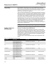
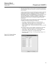
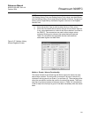
Table 3-3 provides details of the Function Codes supported by the 3095FC.
Table 3-3. Modbus Function
Codes
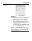
General Tab
The General tab sets the basic communication parameters.
See Figure 3-25 on page 3-42
1. Select Configure > Modbus > Configuration > General tab
2. Select the Modbus Type. The Modbus protocol supports two modes
of transmission ASCII and RTU. All devices in the same
communications must be configured with the same mode of
transmission.
• American Standard Code for Information Interchange (ASCII) –
allows additional time intervals of up to one second to occur
between characters without causing an error. This allows the
messages to be read with the use of a dumb terminal. Each
character is divided into two 4-bit parts that are represented by
their hexadecimal equivalent. The ASCII mode uses twice as
many characters as the RTU mode. Each character sent is
composed of a Start bit, 8 or 7 Data bits, and one or two Stop bits
with Even, Odd, or No parity. ASCII mode uses Longitudinal
Redundancy Checking (LRC) error checking
Code Meaning Action
01 Read Logic Coil Status Obtain current status (ON/OFF) of a group of
logic coils (outputs)
02 Read Discrete Input Status Obtain current status (ON/OFF) of a groups of
Discrete Inputs
03 Read Output Registers (Holding) Obtain current binary value in one or more
holding requests
04 Read Input Registers Obtain current binary value in one or more binary
registers
05 Force Single Logic Coil Force logic coil to a state of ON or OFF.
Acknowledge Alarm or Event request
06 Preset Single Holding Register Place a specific binary value into a holding
register
15 Force Multiple Logic Coils Force a series of consecutive logic output coils
to defined ON or OFF states.
16 Preset Multiple Holding Registers Place specific binary values into a series of
consecutive holding registers.