


Reference Manual
00809-0100-4832, Rev AA
March 2004
C-9
Rosemount 3095FC
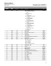
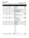
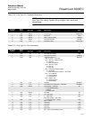
10 R/W UINT 8 1 RTS Communications Port 2 RTSCM2
11 R/W UINT 8 1 Clear Config Memory CLREEP
12 R/W UINT 8 1 I/O Scan Enable IOSCAN
13 R/W UINT 8 1 Auxiliary Output 2 On AUX2
14 R/W UINT 8 1 Auxiliary Output 1 On AUX1
15 R/W UINT 8 1 Cold (Hard) Start options:
0 = None
1 = Restore config from flash / defaults
2 = Restore config and clear alarm / event logs
3 = Restore config and clear ROC displays
4 = Restore config and clear FSTs
5 = Restore config and clear history
6 = Restore config and clear all of above
COLD
16 R/W UINT 8 1 Warm Start WARM
17 R/W UINT 8 1 Read I/O IOREAD
18 R/W UINT 8 1 Write to Config Memory WRITE
19 R/W UINT 8 1 Config Memory Write Complete COMPLT
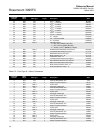
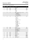
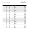
20 R/W UINT 8 1 Event Log Flag (FloBoss 100-series and FloBoss
500-series)
Init History (FloBoss 407 and ROC300-series with a
FlashPAC)
EVTFLAG
21 R/W UINT 8 1 LOI Security On LOISEC
22 R/W UINT 8 1 Comm Port 1 Security On COM1SEC
23 R/W UINT 8 1 Comm Port 2 Security On COM2SEC
24 R/W UINT 8 1 Termination Type Installed:
1 = 4 point I/O – DI, DO, AI, AO Installed
2 = 4 point I/O – No I/O Installed
3 = 6 point I/O – I/O Installed
4 = 6 point I/O – No I/O Installed
FLAG24
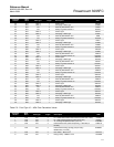
25 R/W UINT 8 1 Comm Port Pass Through Mode:
0 = No Pass Through.
1 = LOI to COM1
2 = COM1 to LOI
3 = LOI to COM2
4 = COM2 to LOI
5 = COM1 to COM2
6 = COM2 to COM1
FLAG25
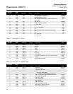
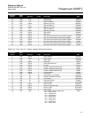
26 R/W UINT 8 1 6 Point I/O Setup Flag:
Bit 0:
0 = AI1
1 = DI1
Bit 1:
0 = AI2
1 = DI2
Bit 2:
0 = AO
1 = DO1
Bit 4:
0 = PI1
1 = DI3
Bit 5:
0 = PI2
1 = DI4
Bits 3, 6 and 7 – Not Used
FLAGE26
27 R/W UINT 8 1 Flag 27 FLAG27
28 R/W UINT 8 1 Flag 28 FLAGE28
29 R/W UINT 8 1 Flag 29 FLAG29
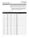
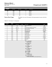
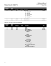
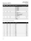
Parameter
Number
Read-
Write
Data Type Length Description Abbr.