


Reference Manual
00809-0100-4832, Rev AA
October 2004
3-19
Rosemount 3095FC
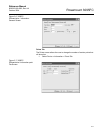
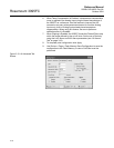
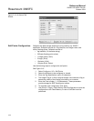
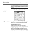
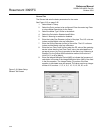
AI Alarms Tab
See Figure 3-14 on page 3-20.
The AI Alarms tab sets the alarm parameters for the AI point.
1. Select Device > I/O > AI Points > Alarms
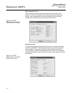
2. Set the values for the different alarms. There are six different alarms:
• Low Alarm: The limit value, in engineering units, to which the I/O
must fall to generate a Low Alarm.
• High Alarm: The limit value, in engineering units, to which the I/O
must rise to generate a High Alarm.
• LoLo Alarm: The limit value, in engineering units, to which the I/O
must fall to generate a LoLo Alarm. The value is set lower than the
Low Alarm.
• HiHi Alarm: The limit value, in engineering units, to which the I/O
must rise to generate a HiHi Alarm. The value is set higher than
the High Alarm.
• Rate Alarm: The value, in engineering units, that represents the
maximum amount of change permitted between updates. If the
change is equal to, or greater than this value, an alarm is
generated. To disable the Rate Alarm without disabling the other
alarms, the Rate Alarm value must be set greater than the Span of
the Analog Input or TDI.
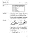
• Alarm Deadband - The value, in engineering units, is an inactive
zone above the Low Alarm limits and below the High Alarm limits.
The purpose of the Alarm Deadband is to prevent the alarm from
being continuously set and cleared when the input value is
oscillating around the alarm limit. This prevents the Alarm Log
from being over-filled with data.
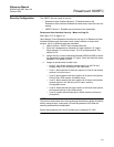
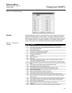
3. Select RBX Alarming
• Disabled if limit alarms are not necessary for this point. Even if
Alarming is Disabled, the Point Fail (hardware reports a
malfunction) alarm and Manual (Scanning Disabled) indicators
can still occur. To conserve Alarm Log space, only Enable
Alarming when necessary.
• If the host PC is configured to receive field-initiated calls, a
Report-by-Exception (RBX) option is available.
• On Alarm Set - When the point enters an alarm condition, the
3095FC generates a RBX message.
• On Alarm Clear - When the point leaves an alarm condition,
the 3095FC generates a RBX message.
• On Alarm Set and Clear - When point enters and leaves an
alarm condition, the 3095FC generates a RBX message.
4. To complete point configuration click Apply.
5. Use Device > Flags > Flash Memory Save Configuration to save the
configuration to the Flash Memory in case a Cold Start must be
performed.