


Reference Manual
00809-0100-4832, Rev AA
October 2004
Rosemount 3095FC
3-53
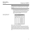
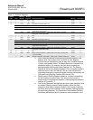
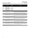
49 Deadband, Float Scale 1 3, 4, 6, 16 The Deadband to Float Scale conversion changes the Deadband pint data to
an integer for transmission to the host. The number of the Convert Code
specifies which floating point scaling value is to be used for the conversion.
50 Deadband, Float Scale 2 3, 4, 6, 16
51 Deadband, Float Scale 3 3, 4, 6, 16
52 Deadband, Float Scale 4 3, 4, 6, 16
53 Deadband, Float Scale 5 3, 4, 6, 16
54 Deadband, Float Scale 6 3, 4, 6, 16
55 Deadband, Float Scale 7 3, 4, 6, 16
56 Deadband, Float Scale 8 3, 4, 6, 16
57 to 64 No Conversion – –
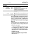
65 IEEE Floating Point Number 3, 4, 16 Places byte 0 an byte 1 in register xxxxx; bye 2 and bye 3 are placed in
register xxxxx + 1. this places a 4-byte floating point value into two, 2-byte
registers to allow integer values to be transmitted. Code 66 does the same as
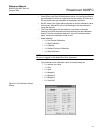
Coded 65 regardless of the Byte Order field in the Modbus Configuration
screen. Register xxxxx byte 0, byte 1 register xxxxx + 1 byte 2, byte 3.
66 IEEE Floating Point Number 3, 4, 16
67 IEEE Floating Point Number 3, 4, 16 Code 67 reverses byte 0 and byte 1 order in register xxxxx; reverses byte 2
and byte 3 order in register xxxxx + 1. This places a 4-byte floating point value
into two, 2-byte registers to allow integer values to be transmitter. Code 68
does the same as Code 67 regardless of the Byte Order field in the Modbus
Configuration screen. Register xxxxx byte 1, byte 0 Register xxxxx + 1 byte 3,
byte 2.
68 IEEE Floating Point Number 3, 4, 16
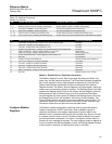
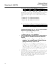
69 IEEE Floating Point Number 3, 4, 16 Code 69 places byte 2 and byte 3 in register xxxxx; byte 0 and byte 1 are
placed in register xxxxx + 1. This places a 4-byte floating point value into two,
2-byte registers to allow integer values to be transmitted. Code 70 does the
same as Code 69 regardless of the Byte Order field in the Modbus
Configuration screen. Register xxxxx byte 2, byte 3 Register xxxxx + 1 byte 0,
byte 1.
70 IEEE Floating Point Number 3, 4, 16
71 IEEE Floating Point Number 3, 4, 16 Code 67 reverses byte 2 and byte 3 order in register xxxxx; reverses byte 0
and byte 1 order in register xxxxx + 1. This places a 4-byte floating point value
into two, 2-byte registers to allow integer values to be transmitter. Code 72
does the same as Code 71 regardless of the Byte Order field in the Modbus
Configuration screen. Register xxxxx + 1byte 1, byte 0.
72 IEEE Floating Point Number 3, 4, 16
73 IEEE Floating Point Number 3, 4, 6, 16 Convert Codes 73 and 74 send the IEEE formatted floating point number as
four bytes with a single register request. Only the byte order is changed:
Function Code 73 loads register xxxxx in byte 2, byte 3, byte 0, byte 1 order.
Function code 74 does the same as Function Code 73 regardless of the Byte
Order field in the Modbus Configuration screen.
74 IEEE Floating Point Number 3, 4, 6, 16
75 to 255 No Conversion – –
Convert
Code
Description
Slave
Function
Definition