


Reference Manual
00809-0100-4832, Rev AA
October 2004
2-5
Rosemount 3095FC
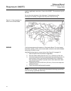
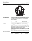
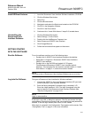
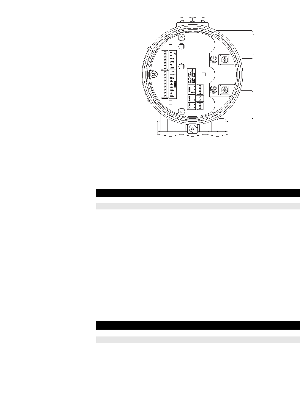
Figure 2-2. Wiring Terminals
Power Supply Wiring The terminals are labeled CHG+ for positive power connection and CHG- for
negative power connection on a label on the termination board. These
connections provide the input voltage and power for the battery charging
circuitry. The maximum voltage that can be applied to the CHG+ / CHG-
terminals is 28 Volts dc.
RTD Wiring Temperature is input through the Resistance Temperature Detector (RTD)
probe and circuitry. The 3095FC provides terminations for a 2- or 3-wire
100-ohm platinum RTD with a IEC 751 curve. The RTD has an alpha (α)
equal to 0.00385.
The RTD mounts directly to the piping using a thermowell. RTD wires should
be protected by a metal sheath or by a conduit connected to a conduit wiring
fitting on the enclosure. The RTD wires connect to the three screw terminals
designated “RTD” on the Termination Board (see Figure 2-2).
Wiring between the RTD and 3095FC should be shielded wire, with the shield
grounded only at one end to prevent ground loops. Ground loops cause RTD
input signal errors.
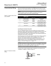
Table 2-1 displays the RTD terminal connections for the various RTD probes.
Table 2-1. RTD Signal Routing
Pin Signal Description
1 CHG+ Battery 8.0 to 28 V Power
2 CHG– Battery Common
Terminal Designation 3-Wire RTD 2-Wire RTD
RTD + Signal positive input RTD + RTD +
RTD + Signal positive input RTD + Jumper to RTD +
RTD RET Return reference RTD RET RTD RET