


Reference Manual
00809-0100-4832, Rev AA
October 2004
2-9
Rosemount 3095FC
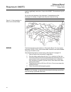
Pipelines Without Cathodic Protection
The pipeline may provide an adequate earth ground and the 3095FC could
mount directly on the meter run using an orifice plate. Use a ground system
tester to make sure the pipeline to earth impedance is less than 2 ohms. If the
pipeline to earth impedance is greater than 2 ohms, the 3095FC installation
should be electrically isolated and a ground rod or grid grounding system
installed. If the pipeline provides an adequate ground, a separate ground rod
or grid system may not need to be installed.
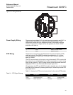
POWER SUPPLY The 3095FC accepts input voltages from 8.0 volts to 28 volts at the power
terminals (CHG+ / CHG-) with no external current limiting (internal current
limit is 200 mA). The CHG+ / CHG- terminal can accommodate up to 16 AWG
wire.
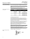
To adequately meet the needs of the 3095FC system, it is important to
determine the total power consumption and size of solar panel requirements
accordingly. To determine the total 3095FC power consumption, be sure to
add the power consumption (in mW) of any other devices used with the
3095FC in the same power system. The maximum power for DC voltage
sources is 130 mW not including the battery charging.
Convert the total value (in mW) to Watts by dividing it by 1000.
mW / 1000 = Watts
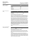
For selecting an adequate power supply, use a safety factor (SF) of 1.25 to
account for losses and other variables not factored into the power
consumption calculations. To incorporate the safety factor, multiply the total
power consumption (P) by 1.25.
PSF = P x 1.25 = _____ Watts
To convert PSF to current consumption in amps (ISF), divide PSF by the
system voltage (V) of 12 volts.
ISF = PSF / 12V = _____ Amps
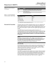
Batteries
Batteries provide power for the 3095FC when the solar panels are not
generating sufficient output. The batteries are three D-size lead-acid batteries
providing 2.5 Amp-hours of current at 6.2 volts.
The batteries are connected in series by the Battery Charger Board to
achieve the required capacity. The battery capacity determines the number of
days of reserve (autonomy) desired.
When the 3095FC is configured as an API compliant Electric Flow
Management (EFM) and requires an internal communications card, a solar
panel, and the internal batteries, the 3095FC should be able to communicate
the API audit trail information once a day to a remote host using no additional
battery source, no additional solar panel, and maintain a 13 day autonomy in
the event that the solar panel is lost.
To determine the system capacity requirements, multiply the system current
load (ISF) on the batteries by the amount of reserve time required. Compute
“ISF” as described above. The equation is as follows:
System Requirement = ISF amps x Reserve hrs = _____ amp-hrs