


Reference Manual
00809-0100-4832, Rev AA
October 2004
Rosemount 3095FC
2-4
supplies significantly more than 1 Amp to the 3095FC. The maximum input is
28 volts.
Do not allow the batteries to fully discharge. If the batteries are fully
discharged, the battery charger board may enter thermal limiting.
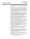
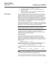
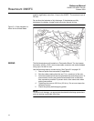
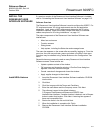
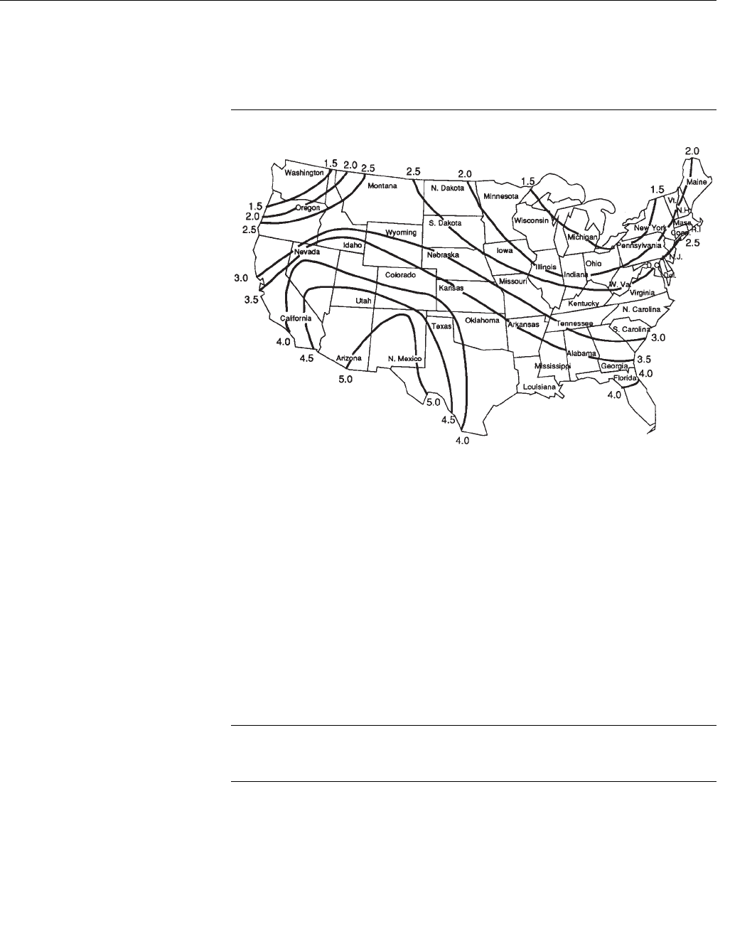
Figure 2-1. Solar Insolation in
Hours for the United States
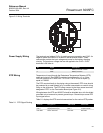
WIRING The field terminals are all located on a Termination Board. The input power
termination (CHG+ / CHG-) uses a removable connector and accommodates
wiring up to 16 AWG in size.
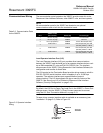
Use the following steps to connect wiring. See Figure 2-2 on page 2-5.
1. Remove power from transmitter (if applicable)
2. Strip the rubber coating from the end (
1
/4-in. maximum) of the wire.
3. Insert the bared end into the clamp beneath the termination screw. To
prevent short circuits, the inserted wires should have as little bare
wire exposed as possible.To prevent strain, allow some slack when
making connections.
4. Tightening the screw to 0.25 N-m (2.2 lb-in.). Do not over torque the
connector screws.
5. Check the polarity before applying power.
NOTE
To avoid circuit damage, use appropriate electrostatic discharge precautions,
such as wearing a grounded wrist strap.