


Reference Manual
00809-0100-4832, Rev AA
October 2004
3-47
Rosemount 3095FC
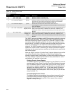
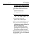
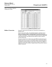
Table 3-6. Modbus Events and
Alarms Log Content
Modbus - Detailed Point / Parameter Information
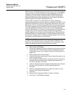
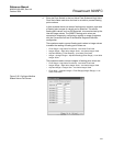
The Modbus Special Function Table (point type 39) returns the Event Log,
Alarm Log, and the Historical Archives. The Event/Alarm Register (parameter
#0), Hourly (periodic) History Index Register (parameter #1), and the Daily
History Index Register (parameter #2) can be configured to the desired
Register Number. The History Archive Register is a single register, which can
contain one or more history points for retrieval. The Starting History Point field
contains the Starting History Point for the History Archive Register, while the
Ending History Point is the last history point to be included in the History
Archive Register. All history points in between the Starting History Point and
the Ending History Point are included in the History Archive Register. The
Type of History Archive can only be one of two choices: Hourly or Daily. The
Conversion Code can be used to convert the history values. However, the
Conversion Code does not affect the time and date stamp.
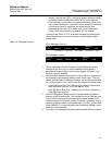
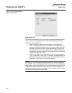
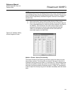
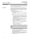
Configure Modbus
Registers
The Modbus register configuration tables are used to associate Modbus
register numbers with 3095FC point data. When a Modbus request is
received, the Modbus user program searches the function table for the
Modbus function requested, starting with the first table entry down to the last.
If a register number match is found, it builds a response based on the point
type and parameter configured in the table. If no register number match is
located, an error message is returned. The user program locates a register as
long as it matches the Starting Register number, the Ending Register number,
or any number in between for that particular entry in the table.
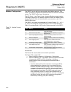
Byte Content of Event Log Record Contents of Alarm Log Record
1 – 2 Operator change bit map (16-bit) Alarm change bit map (16-bit integer)
3 – 4 Modbus register number of variable (16-bit integer) Modbus register number of variable (16-bit integer)
5 –8 Time Stamp (HHMMSS; 32-bit floating point) Time Stamp (HHMMSS; 32-bit floating point)
9 – 12 Date Stamp (HHMMSS; 32-bit floating point) Date Stamp (HHMMSS; 32-bit floating point)
13 – 16 Previous value of variable (32-bit floating point) Current (alarmed) value of variable (32-bit floating point)
17 – 20 Current (new) value of variable ((32-bit floating point Unused at the current time (zero filled when transmitted to the master)
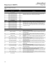
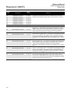
Bit Operator Change Bit Map Alarm Changed Bit Map
0 Fixed value - change to an EU value on an I/O point in Manual mode Not used
1 Zero scale - change to the 0% Adjusted on an AI Not used
2 Full scale - change to the 100% Adjusted on an AI Not used
3 Operator entry work value - change to any parameter other than those described Not used
5 Fixed / variable flag - change to manual mode for an I/O point Manual alarm
6 Table entry change - change to Modbus Function Tables Status change alarm
7 System command change - events logged by system (power up) No flow alarm
8 Not used Point fail alarm
9 Operator change event identifier bit Operator change even identifier bit
10 LoLo Limit - change to LoLo alarm parameter LoLo Alarm
11 Low Limit - change to Low alarm parameter Low Alarm
12 HiHi Limit - change to HiHi alarm parameter HiHi Alarm
13 High Limit - change to High alarm parameter High Alarm
14 Rate of change limit - change to Rate Alarm parameter Rate Alarm
15 Not used Set/clear alarm (1=set, 0=clear)