8 - 11
–+
ELEC
IGNITION SYSTEM
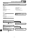
C0NTINUITY
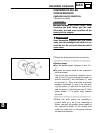
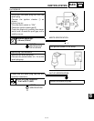
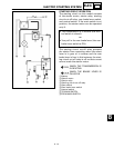
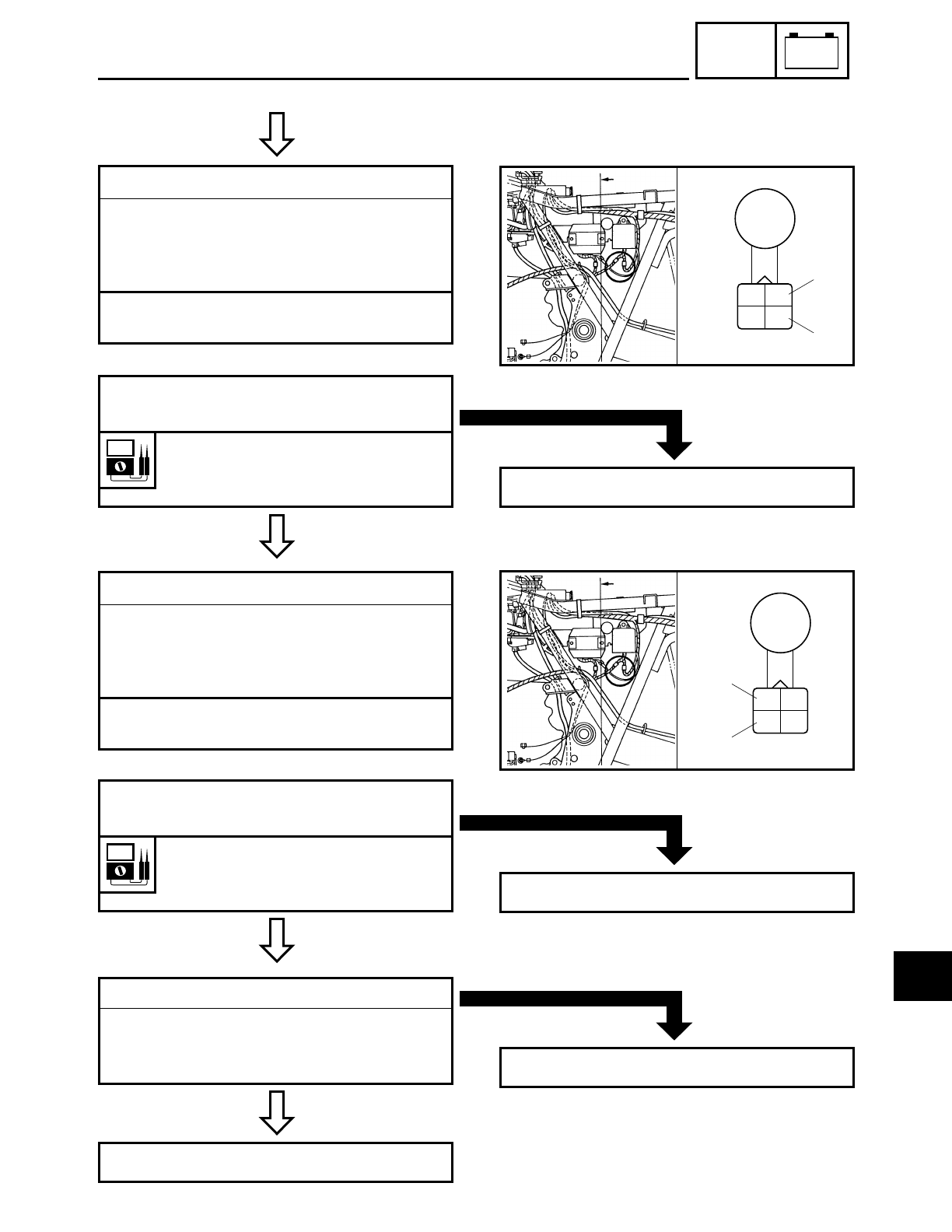
7.Pickup coil resistance
● Disconnect the CDI magneto coupler
from the wire harness.
● Connect the pocket tester (Ω × 100) to
the pickup coil terminal.
Tester (+) lead → White/Green terminal 1
Tester (–) lead → White/Red terminal 2
*
Br
W/G
B
W/R
2
1
MEETS
SPECIFICATION
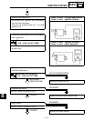
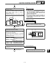
● Check the pickup coil for the specified
resistance.
Pickup coil resistance:
189~ 231 Ω at 20˚C (68˚F)
(White/Green – White/Red)
OUT OF SPECIFICATION
Replace the pickup coil.
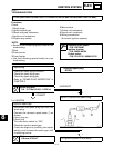
8.Source coil resistance
● Disconnect the source coil coupler from
the wire harness.
● Connect the pocket tester (Ω × 100) to
the source coil terminal.
Tester (+) lead → Brown terminal 1
Tester (–) lead → Black terminal 2
Br
W/G
B
W/R
2
1
MEETS
SPECIFICATION
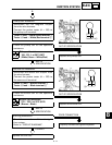
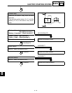
● Check the source coil for the specified
resistance.
Source coil resistance:
270 ~ 330 Ω at 20˚C (68˚F)
(Brown – Black)
OUT OF SPECIFICATION
Replace the source coil.
CORRECT
9.Wiring connection
● Check the connections of the entire igni-
tion system.
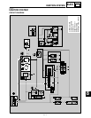
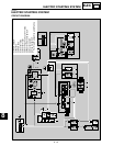
Refer to “CIRCUIT DIAGRAM”.
Replace the CDI unit.
POOR CONNECTION
Properly connect the ignition system.
8


