


4 - 52
ENG
ENGINE ASSEMBLY AND ADJUSTMENT
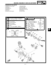
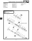
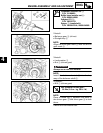
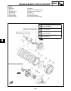
Crankshaft installer set 1:
P/N. YU-90050
Buffer boss installer set 2:
P/N. 90890-04088
Adapter #11 3:
P/N. YM-33279
Spacer 4 (crankshaft):
P/N. YM-90070-A, 90890-04060
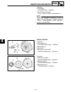
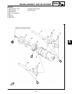
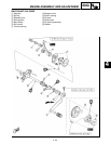
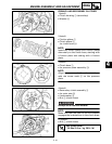
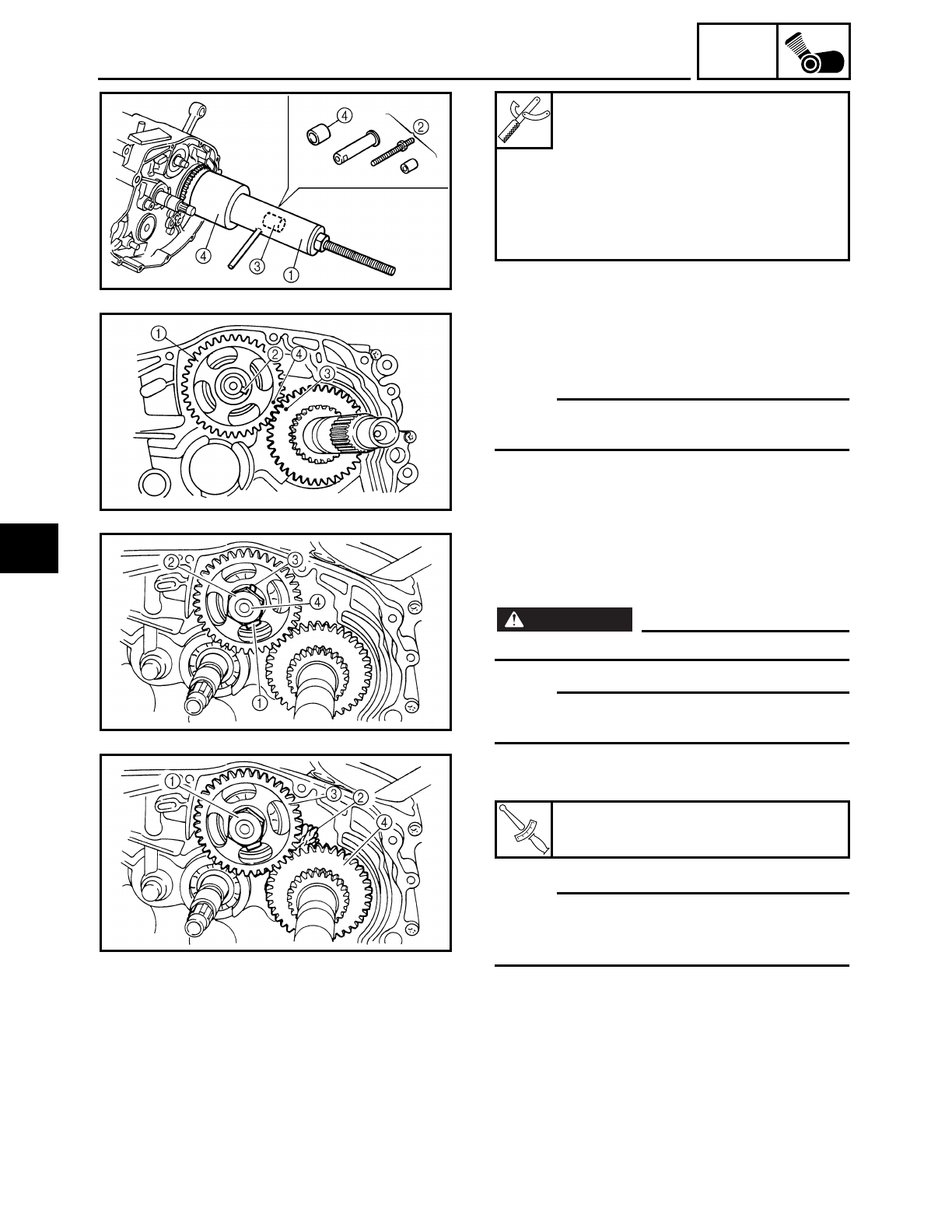
2.Install:
● Balancer gear 1 (driven)
● Straight key 2
NOTE:
Align the drive gear mark 3 with the driven
gear mark 4.
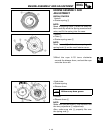
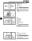
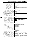
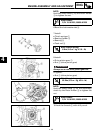
3.Install:
● Lock washer 1
● Nut 2 (driven gear)
WARNING
Always use a new lock washer.
NOTE:
Install the lock washer tab 3 into the key
way of the balancer shaft 4.
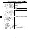
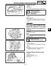
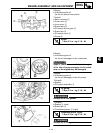
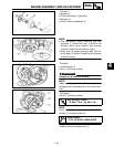
4.Tighten:
● Nut 1 (driven gear)
NOTE:
Place a folded rag 2 between the teeth of
the driven gear 3 and drive gear 4 to lock
them.
5.Bend the lock washer tab.
T
R
.
.
Nut (balancer driven gear):
50 Nm (5.0 m • kg, 36 ft • lb)
4