


6 - 36
DRIV
FINAL DRIVE GEAR AND DRIVE SHAFT
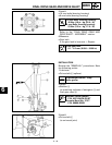
Thrust washer selection
1.Measure/Select:
● Ring gear thrust clearance “C”
*********************************
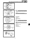
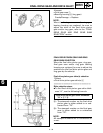
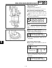
Thrust clearance measurement steps:
●Place four pieces of Plastigauge
between
originally fitted thrust washer and ring
gear.
●Install the ring gear assembly and tighten
the bolts to specification.
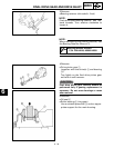
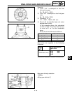
NOTE:
Do not turn the shaft drive and ring gear
when measuring clearance with Plasti-
gage
.
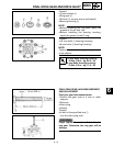
●Remove the ring gear assembly.
●Measure the thrust clearance. Calculate
width of flattened Plastigauge
1.
●If the out of specification, select the cor-
rect washer.
T
R
.
.
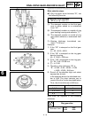
10 mm Bolts (bearing housing):
40 Nm (4.0 m • kg, 29 ft • lb)
8 mm Bolts (bearing housing):
23 Nm (2.3 m • kg, 17 ft • lb)
Ring gear thrust clearance:
0.1 ~ 0.2 mm (0.004 ~ 0.008 in)
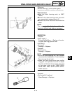
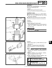
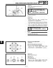
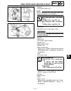
Thrust washer selection steps:
●Select suitable thrust washer by the fol-
lowing chart.
● Repeat measurement steps until the ring
gear thrust clearance is within the speci-
fied limits.
*********************************
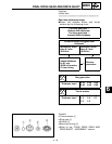
Thrust washer
Thickness (mm)
1.2 1.7 2.0
1.4 1.8 2.1
1.6 1.9
Ring gear thrust clearance:
0.1 ~ 0.2 mm (0.004 ~ 0.008 in)
6