


6. TROUBLESHOOTING
6-16
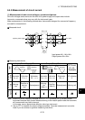
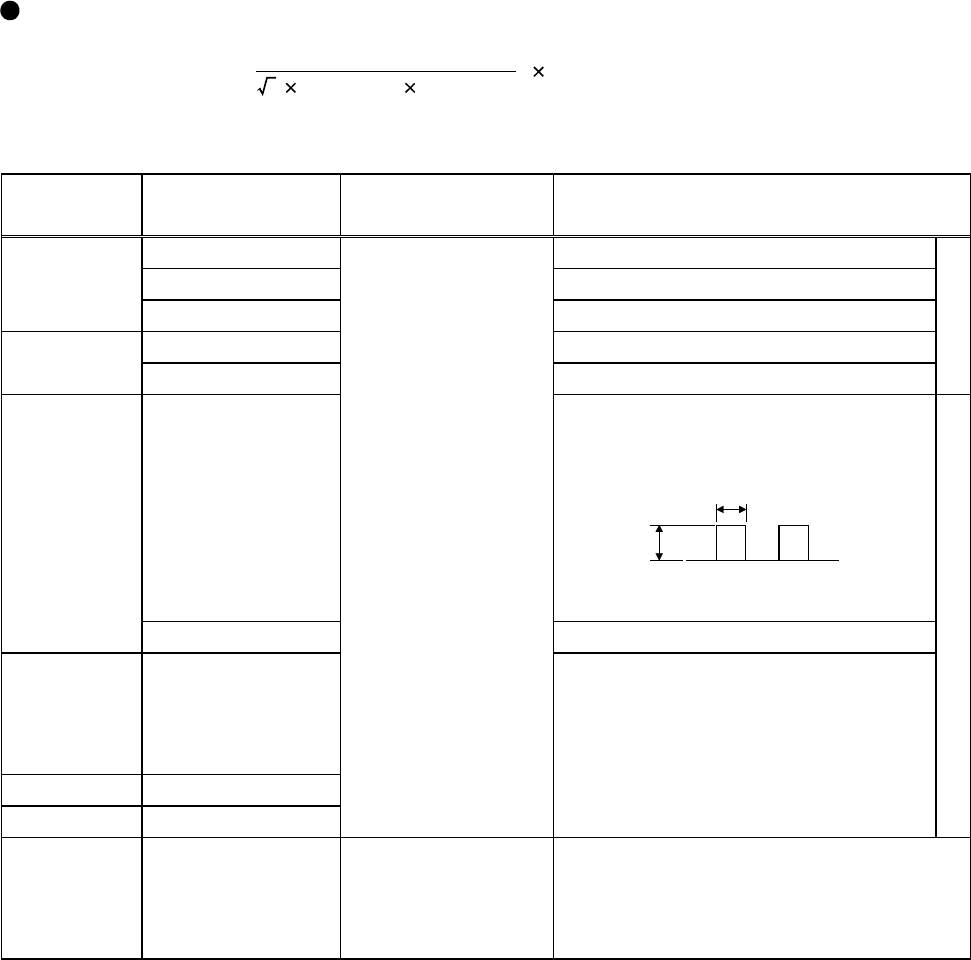
(2) Measurement of power factor
The power factor cannot be measured with a commercially available power-factor meter which is
designed to measure the phase difference between a voltage and a current. Measure the power
supply side voltage, current and power, then calculate the power factor using the following
expression. Calculate the power factor of the motor alone from the output side voltage, current and
power.
Expression
P
ower factor (%) 100
Power (W)
current (A)voltage (V)
3
=
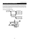
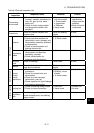
(3) Measurement of control circuit signal values
Signal
Name
Measured
Terminals
Measuring
Instrument
Measured Value
Across 2(+)-5 DC0 to 5V/0 to 10V
Across 1(+)-5 DC0 to
±
5V to 0,
±
10V
Speed
setting signal
Across 4(+)-5 DC4 to 20mA
Across 10(+)-5 DC5V
Speed setting
power supply
Across 10E(+)-5 DC10V
"5" is common.
Across FM(+)-SD
Approx. 5VDC at maximum speed
(Without meter)
DC8V
T1
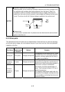
Pulse width T1: Use Pr. 900 to adjust.
Meter signal
Across AM(+)-5 Approx. 10VDC at maximum speed
Start signal
Selection
signal
Across STF, STR,
RH, RM, RL, JOG,
RT, AU, STOP,
CS(+)-SD
Reset Across RES(+)-SD
Output stop Across MRS(+)-SD
Moving-coil type
(Tester or like may
be used)
(Internal resistance
50k
Ω
or more)
When terminals are open,
20 to 30VDC
ON-time voltage 1V max.
SD is common.
Continuity check (*1)
<At OFF> <At ON>
Across A-C Discontinuity Continuity
Alarm signal
Across A-C
Across B-C
Moving-coil type
(e.g. tester)
Across B-C Continuity Discontinuity
(*1) When the Pr. 195 "A, B, C terminal function selection" setting is positive logic.