


3. WIRING
3-5
3
3.2 Wiring of the Main Circuit Terminals
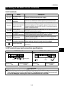
3.2.1 Terminals
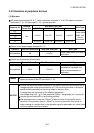
Symbols Name Description
R, S, T
AC power input
terminals
Connect to the commercial power supply.
U, V, W
Motor connection
terminals
Connect to a dedicated variable-speed synchronous motor.
R1, S1
Control circuit power
supply terminals
Connected to the AC power input terminals R, S. To retain
the alarm display and alarm output, remove the jumpers from
the terminal block (across R-R1 and S-S1) and input external
power to these terminals.
P/+, PR
Brake resistor
connection terminals
Disconnect the jumper from terminals PR-PX and connect the
FR-ABR brake resistor (option).
P/+, P1
DC reactor
connection terminals
Disconnect the jumper from terminals P/+-P1 and connect the
FR-BEL power factor improving DC reactor (option).
P/+, N/- DC terminals
Connect to the BU brake unit (option) or FR-HC high power
factor converter (option).
PR, PX
Built-in brake circuit
connection terminals
When the jumper is connected across terminals PX-PR
(factory setting), the built-in brake circuit is enabled.
Ground terminals
Terminals for connection of the ground cables. (There are two
terminals.)
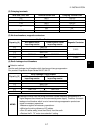
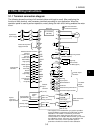
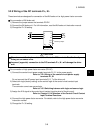
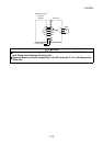
3.2.2 Terminal layout and connection specifications
AX520-0.5, 1.0K AX520-1.5K to 3.5K
Layout
R
R1
STUVWPR
S1 P1
PXP/
+
N/
-
Charge lamp
Jumper
Layout
R
R1
STUVW PR
S1
P1
PX
N/
-
P/
+
Charge lamp
Jumper
Screw size
M4
Tightening torque
1.5N
•
m
Screw size
M4
Tightening torque
1.5N
•
m
CAUTION
Tighten the terminal screws to the specified torque. Undertightening can cause an
inter-terminal short circuit or malfunction. Overtightening can cause the screws and
unit to be damaged, resulting in a short circuit malfunction or the like.