


8 PARAMETER FUNCTIONS
8-44
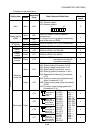
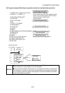
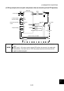
(6) Program example (Switching the operation mode to communication operation)
10 OPEN "COM1 : 9600,E,8,2,HD" AS #1
80 A$=MID$(D$,I,1)
90 A=ASC(A$)
100 S=S+A
110 NEXTI
120 D$=CHR$(&H5)+D$+RIGHT$(HEX$(S),2)
130 PRINT#1,D$
140 GOTO 50
1000 REC
1010 IF LOC(1)=0 THEN RETURN
1020 PRINT "RECEIVE DATA"
1040 RETURN
60 S=0
40 COM(1)ON
50 D$= "01FB10002"
20 COMST1,1,1:COMST1,2,1
30 ON COM(1)GOSUB REC
70 FOR I=1 TO LEN(D$)
1030 PRINT INPUT$(LOC(1),#1)
Initial setting of input file
: Communication file opening
: Interrupt definition at data receive
: Circuit control signal (RS (ON in data-receivable
status), ER (unit ready signal)) ON/OFF setting
Transmission data setting
: Interrupt enable
Sum code calculation
: Addition of control and sum codes
Data transmission
Interrupt data receive
: Interrupt occurrence at data receive
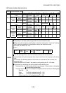
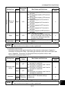
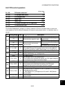
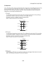
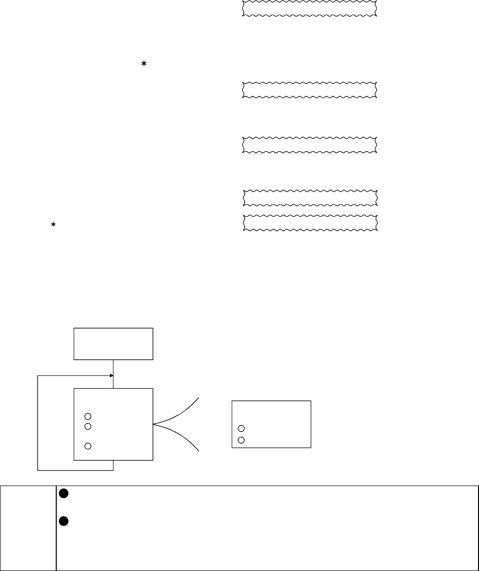
General flowchart
Line number
Input file
initial setting
Interrupt
10
to
40
50
to
140
Transmission
data processing
Data setting
Sum code
calculation
Data
transmission
1000
to
1040
processing
Receive data
Data import
Screen display
NOTICE
The drive unit does not accept data from the computer if it is in error. Hence, always
insert a data error retry program in the user program.
Since the communication of any data, e.g. run command, monitor, is started from
the computer, the drive unit will not return data without the computer's command.
For monitoring, therefore, design the program to cause the computer to provide a
data read request as required.