


8 PARAMETER FUNCTIONS
8-58
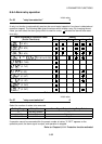
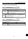
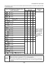
8.7.2 Selection of the control circuit output terminal functions
Initial value
Pr. 190 "RUN terminal function selection" 0
Pr. 191 "SU terminal function selection" 1
Pr. 192 "IPF terminal function selection" 2
Pr. 193 "OL terminal function selection" 3
Pr. 194 "FU terminal function selection" 4
Pr. 195 "A, B, C terminal function selection" 99
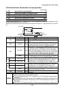
You can select/change the functions of the control circuit output terminals. At the initial values, the
terminal names and signal names match.
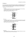
<Setting example>
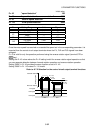
When Pr. 190 = 99, the RUN terminal provides the function of the ABC terminal. In this case, if the
Pr. 195 setting is "99", the RUN terminal has the same function as that of the ABC terminal, and the
same signal is available from the two terminals.
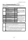
Setting
Positive
logic
Negative
logic
Signal
Name
Operation at Positive Logic Setting
("ON" and "OFF" are reversed for negative logic setting)
0 100 RUN
"ON" during motor operation, "OFF" during voltage braking
operation or stop.
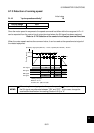
1 101 SU
Turns "ON" when the preset speed is reached.
Refer to: 8.7.3 Detection of running speed
2 102 IPF
Turns "ON" on detection of an instantaneous power failure or
undervoltage.
3 103 OL
Turns "ON" when the stall prevention function is activated.
Refer to: 8.5.6 Stall prevention operation level
4 104 FU
5 105 FU2
6 106 FU3
Turns "ON" at the preset speed or more.
Refer to: 8.7.3 Detection of running speed
7 107 RBP
"ON" when the regenerative brake option duty is 85% or higher.
Refer to: Pr. 70 [Section 8.5.5]
8 108 THP
"ON" when the electronic overcurrent protection operation level
is 85% or higher.
Refer to: Section 8.5.8 Other settings
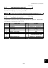
10 110 PU
Turns "ON" when the PU operation mode is selected.
Refer to: Pr. 79 [Section 8.2]
11 111 RY
"ON" in an operation-ready status with the input of the start
signal or during operation.
12 112 Y12
"ON" at the preset output current or higher.
Refer to: 8.7.4 Detection of output current
14 114 FDN
15 115 FUP
16 116 RL
Used for PID control operation.
Refer to: 8.6.3 PID control operation
25 125 FAN Turns "ON" only when the cooling fan fails.
26 126 FIN
"ON" at 85% or higher of the heat sink overheat protection
operation temperature or higher.
98 198 LF
Turns "ON" at a fan failure or communication error alarm.
Refer to: 8.5.8 Other settings
Refer to: 8.6.2 Communication operation from the
PU connector
99 199 ABC
Turns "ON" when the protective function is activated to stop the output.
Refer to: Chapter 6 Troubleshooting
9999
No function
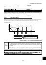
MEMO
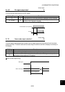
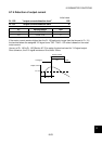
The output terminal set for negative logic is reset when the RES signal is turned
OFF after it has been turned ON once.