


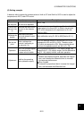
8 PARAMETER FUNCTIONS
8-47
8
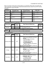
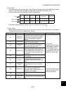
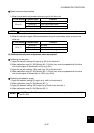
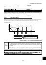
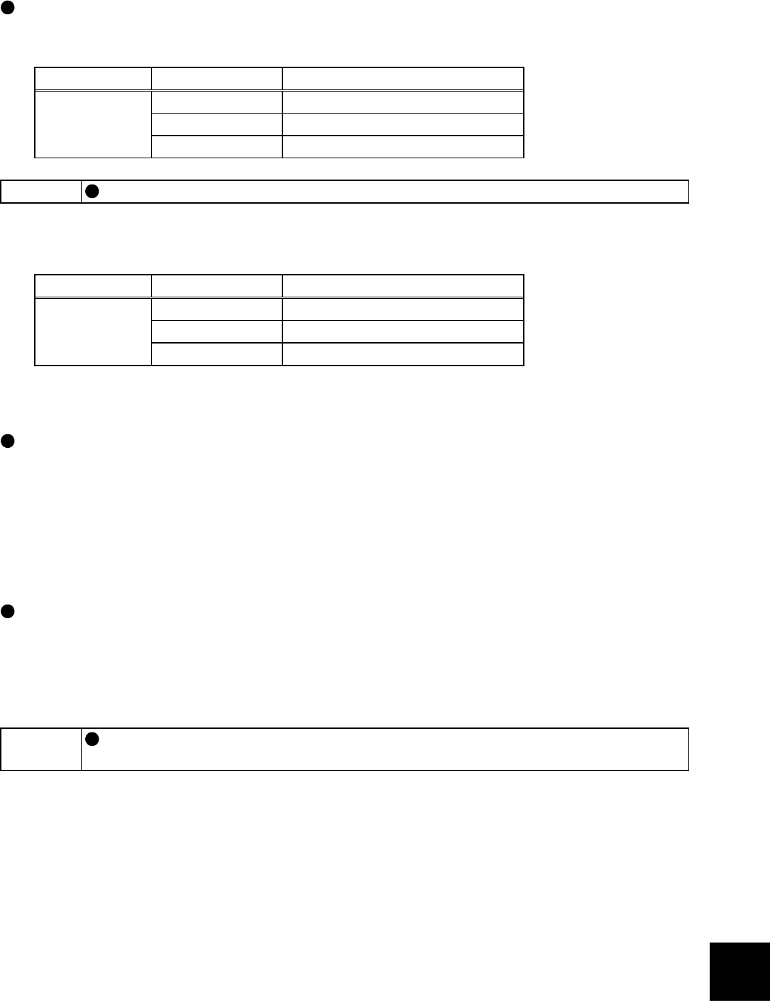
Speed command input method
1) When the set point and process value are input to the drive unit
Pr. 128 Setting Terminal Used Function
Terminal 2 Enter the set point.
Terminal 4 Enter the process value.
20 or 21
Terminal 1 Not used.
MEMO
The signal input to the terminal 1 is added to the set point of the terminal 2.
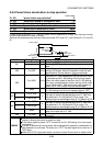
2) When the deviation signal (difference between set point and process value) is input to the
drive unit
Pr. 128 Setting Terminal Used Function
Terminal 2 Not used.
Terminal 4 Not used.10 or 11
Terminal 1 Enter the deviation signal.
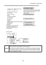
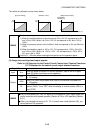
(2) Calibrate the set point and process value as required.
Calibrating the set point
1) Apply the set point setting 0% input (e.g. 0V) to the terminal 2.
2) Make calibration using Pr. 902 [Section 8.3.1]. At this time, enter the speed which the drive
unit should output at the deviation of 0% (e.g. 0Hz).
3) Apply the set point setting 100% input (e.g. 5V) to the terminal 2.
4) Make calibration using Pr. 903 [Section 8.3.1]. At this time, enter the speed which the drive
unit should output at the deviation of 100% (e.g. 60Hz).
Calibrating the detector output
1) Apply the detector setting 0% output (e.g. 4mA) to the terminal 4.
2) Make calibration using Pr. 904 [Section 8.3.1].
3) Apply the detector setting 100% output (e.g. 20mA) to the terminal 4.
4) Make calibration using Pr. 905 [Section 8.3.1].
MEMO
In Pr. 904 and Pr. 905, set the same speeds which were respectively set in Pr. 902
and Pr. 903.