


3. WIRING
3-6
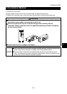
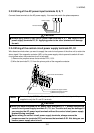
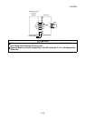
3.2.3 Wiring of the AC power input terminals R, S, T
Connect these terminals to the AC power supply. You need not match the phase sequence.
RST
RST
Power supply
No-fuse breaker
CAUTION
Always apply power to only the AC power input terminals R, S, T and control circuit
power supply terminals R1, S1. Applying power to the other terminals will damage
the unit.
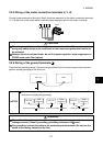
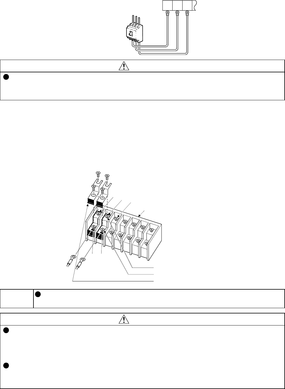
3.2.4 Wiring of the control circuit power supply terminals R1, S1
Wire these terminals when you want to supply the control circuit power of the drive unit to retain the
alarm signal if the magnetic contactor (MC) on the power supply side is opened to switch off main
circuit power when the protective circuit is activated.
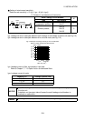
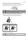
1) Remove the jumpers across the terminals R-R1, S-S1.
2) Wire the terminals R1, S1 from the primary side of the magnetic contactor.
R
S
T
R1 S1
1) Loosen the upper screws.
2) Remove the lower screws.
3) Remove the jumpers.
Main circuit terminal block
MEMO
An error display (E.OC1) will be provided if you turn on the start signal with power
supplied to only the R1 and S1 terminals.
CAUTION
When you have energized the AC power input terminals R, S, T, always energize the
control circuit power supply terminals R1, S1, too. The drive unit may be damaged if
you energize the AC power input terminals without the control circuit power supply
terminals being energized.
Before wiring the control circuit power supply terminals, always remove the
jumpers across the terminals R-R1 and across the terminals S-S1. Not doing so can
cause a power supply short circuit.