


3. WIRING
3-19
3
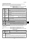
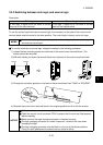
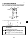
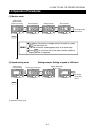
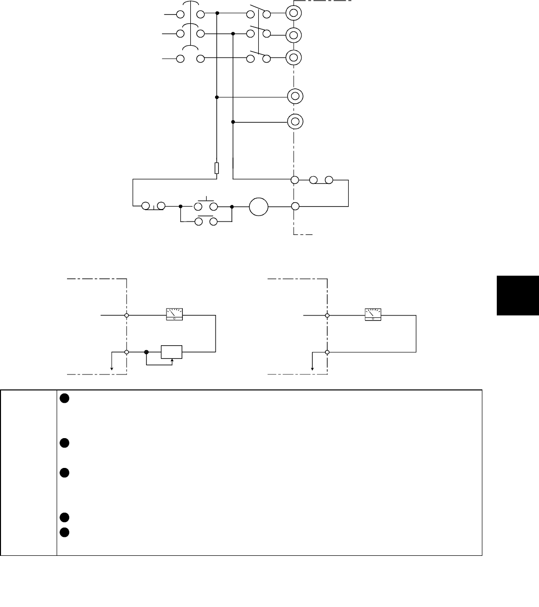
3.3.7 Wiring of the contact output terminals
The following wiring example assumes that when the protective circuit is activated, the magnetic
contactor (MC) on the power supply side is opened to switch off the main circuit power and the
control circuit power of the drive unit is supplied to hold the alarm signal.
R
S
T
R1
S1
B
C
MC
F
MC
NFB MC
Operation-ready
Power supply
Drive unit
Control power
supply
Stop
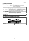
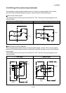
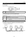
3.3.8 Wiring of the instrument connection terminals
FM
SD
AM
5
Drive unit
Meter
Calibration
resistor
Analog meter
Drive unit
MEMO
The calibration resistor is not needed when the operation panel or parameter unit is
used to make calibration.
Refer to: Pr. 900, Pr. 901 [Section 8.7.5]
When using a shielded cable to wire the terminal AM, connect one shield sheath to
the terminal 5. Leave the other shield sheath open.
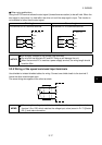
The wiring distance between the drive unit and meter should be as follows.
Terminal FM: Within 200m (analog meter), within 50m (digital meter)
Terminal AM: Within 30m
For the terminal FM, you can connect up to two analog meters in parallel.
For the output signal waveform of the terminal FM, refer to 6.4.5 Measurement of
the circuit current.