


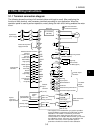
3. WIRING
3-11
3
3.3 Wiring of the Control Circuit Terminals
CAUTION
Use shielded or twisted cables for wiring the control circuit input terminals. Also
run them away from the main circuit wiring and other power cables. Not doing so
can cause a malfunction due to noise.
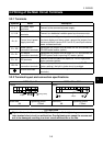
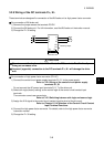
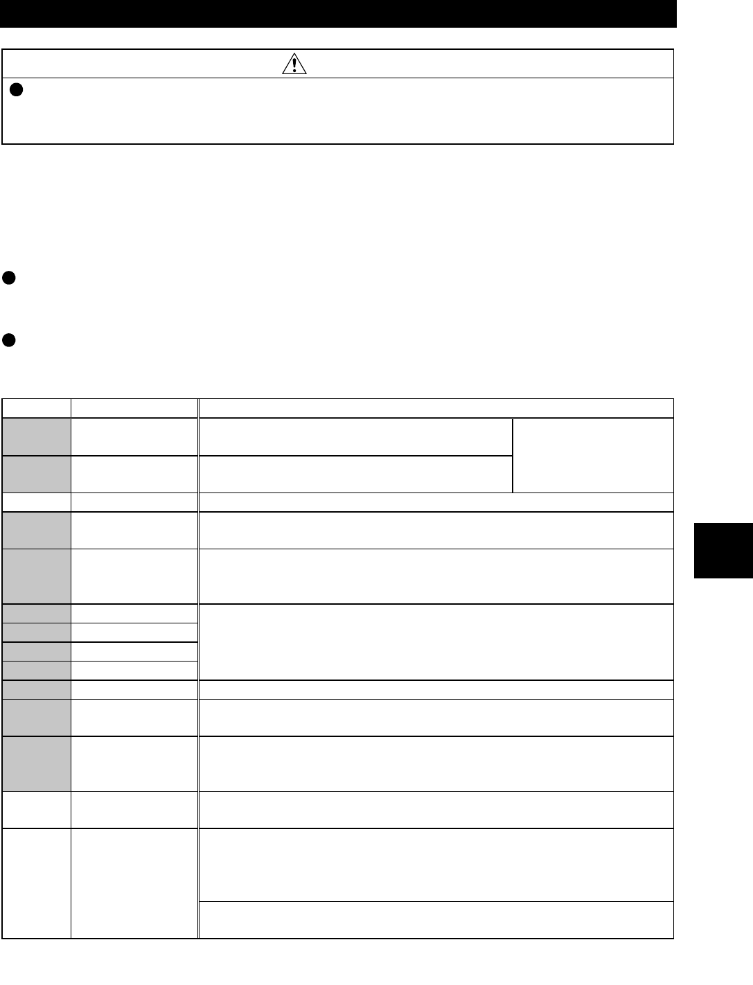
3.3.1 Terminals
After confirming the function of each terminal, use necessary terminals according to your application.
(1) Contact input terminals
Turning the signal across any terminal and common terminal "ON" (closing those
terminals)/"OFF" (opening those terminals) provides the corresponding function as described
below.
The shaded terminal symbols indicate that their functions can be changed.
Refer to: Chapter 8, 8.4 Selection of the Control Circuit Contact
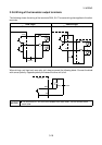
Input Terminal Functions
Symbol Name Description
STF
Forward rotation
start
Turn on this signal to start forward rotation or
turn it off to stop.
STR
Reverse rotation
start
Turn on this signal to start reverse rotation or
turn it off to stop.
Simultaneously
turning on these
signals gives a stop
command.
STOP Start holding Used to self-hold the start signal.
RES Reset
Turn on this signal (for more than 0.1s) to reset the protective circuit
activated. Turn it off after the protective circuit is reset.
MRS Output stop
Turn on this signal (for more than 0.1s) to stop the output and
separate the motor electrically, causing it to coast. Turing it off with
the start signal input will restart the motor at the starting speed.
RH High speed
RM Middle speed
RL Low speed
CS 15 speeds
Combine on/off of these signals as appropriate to select multiple
speeds.
Refer to: Chapter 8, 8.3.2 Variable-speed
operation using contact input signals
JOG JOG mode Turn on this signal to start jog operation.
RT Second selection
Turn on this signal to select the second acceleration/deceleration
time.
AU
Current input
selection
Turn on this signal to choose the speed command of the terminal 4
(current input), enabling operation using the 4 to 20mA current
signal.
SD
Contact input
common
Common to the contact input terminals. (When sink logic is used)
Common terminal used when the contact input terminal is connected
to the transistor output (open collector output) of the external
controller. This terminal can prevent a malfunction caused by a
sneak current.
PC
External
transistor
common
This terminal acts as a common terminal when the contact input
terminal uses source logic.