


8 PARAMETER FUNCTIONS
8-51
8
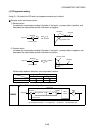
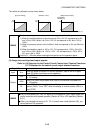
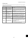
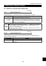
(6) Setting example
A detector which outputs the process values of 4mA at 0
°
C and 20mA at 50
°
C is used to adjust the
temperature to 25
°
C under PID control.
Procedure Description
Determine
the set point.
Determine the set point of
the item to be adjusted.
Set Pr. 128.
Convert the
set point into
%.
Calculate the ratio of the
set point to the detector
output.
When the detector used has the specifications that 0
°
C
is equivalent to 4mA and 50
°
C to 20mA, the set point
25
°
C is 50% because 4mA is equivalent to 0% and
20mA to 100%.
Calibrate the
signals.
Calibrate the set point
input and detector output
as required.
Make calibration using Pr. 902 to 905 [Section 8.3.1].
Set the set
point.
Enter a voltage into
terminal 2 according to
the set point (%).
When the selected feature of the terminal 2 is 0 to 5V, 0V
corresponds to 0% and 5V to 100%. Therefore, enter
2.5V which corresponds to 50%. When entering the set
point from the operation panel, set "50" in Pr. 133.
Operation
Turn "ON" the start signal
and check that the
process value is stable.
Set the proportional band, Pr. 129, slightly larger, the
integral time, Pr. 130, slightly longer, and the differential
time, Pr. 134, slightly shorter, and start operation.
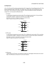
Adjustment
Stabilize the operating
status (detector output).
When stable
Reduce the proportional band, decrease the integral
time, and increase the differential time to increase
the response performance.
When instable
Increase the proportional band, increase the integral
time, and decrease the differential time.