


6. TROUBLESHOOTING
6-5
6
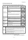
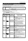
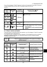
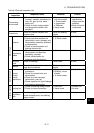
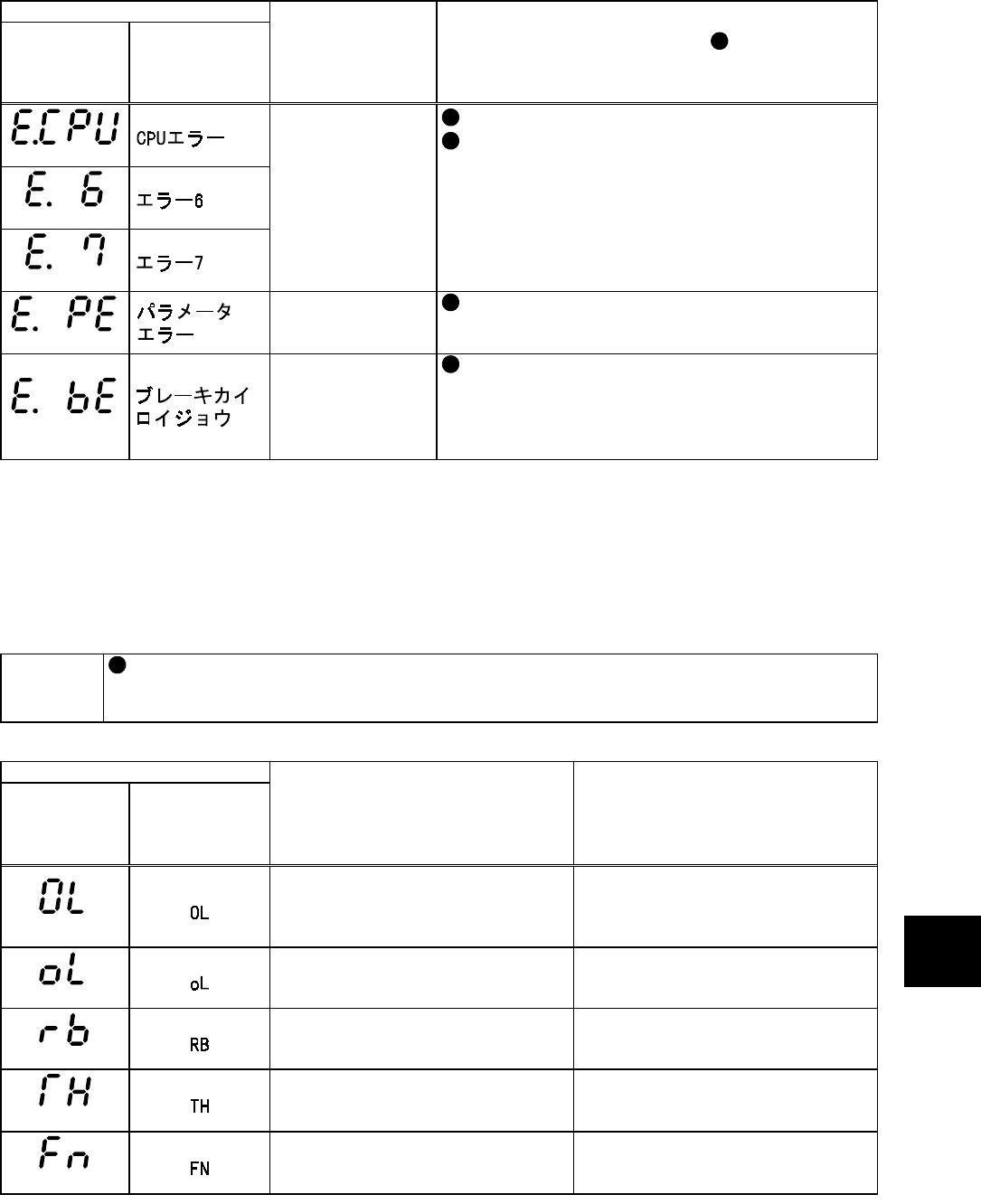
If any of the messages in Table 6-2 appears, the drive unit is assumed to have failed. If the same
message reappears after an alarm reset, immediately replace the drive unit.
Table 6-2
Indication
Operation
panel
(Actual
characters
)
Parameter
unit
Protective
Function Name
Detection Level
Estimated Cause (
)
and
Corrective Action (•)
(E. CPU)
(E. 6)
(E. 7)
CPU fault
The CPU malfunctioned.
The CPU failed.
(E. PE)
Storage device
fault
The storage device failed.
(E. BE)
Brake circuit fault
The regenerative brake circuit failed.
•
If E. BE reappears after a reset, immediately
switch power off.
Leaving power on will overheat the brake
resistor.
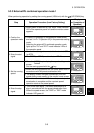
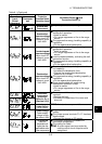
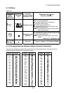
6.1.2 Alarm function activated
If the alarm function is activated during motor operation, any of the displays in Table 6-3 is provided
on the operation panel or parameter unit.
If you ignore the alarm message and continue operation, the fault detection function is activated,
leading to an operation stop. When you noticed that the alarm function had been activated,
immediately remove its cause.
MEMO
That the alarm function has been activated can be exported as an alarm signal.
Refer to: Chapter 8, 8.7.2 Selection of the control circuit output
terminal functions
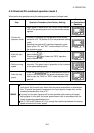
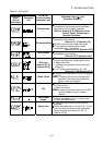
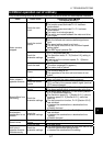
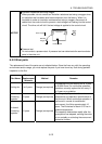
Table 6-3
Indication
Operation
panel
(Actual
characters
)
Parameter
unit
Protective Function Name
Detection Level
Related Protective Function
(OL)
Overload 1
Pr. 22 setting [Section 8.5.6]
Acceleration-time overcurrent,
constant speed-time
overcurrent, deceleration-time
overcurrent, stall stop
(oL)
Overload 2
Main circuit DC voltage more
than 390V
Deceleration-time overvoltage
(RB)
Brake duty
More than 85% of the permissible
value
Deceleration-time overvoltage
(TH)
Motor overheat
More than 85% of the electronic
overcurrent protection level
Electronic overcurrent
protection
(FN)
Fan failure
Cooling fan fault
Refer to: Pr. 244 [Section 8.5.8]
Fin overheat