


8 PARAMETER FUNCTIONS
8-48
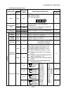
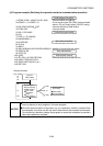
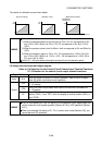
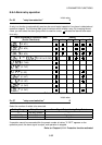
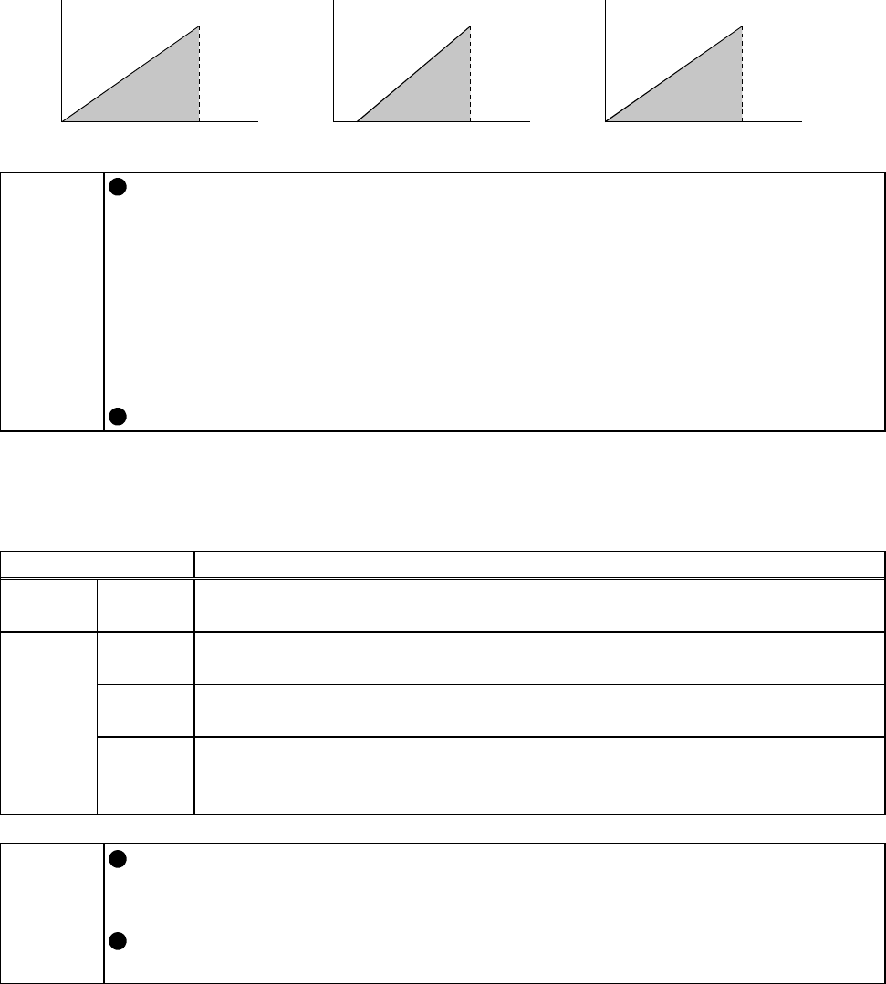
The results of calibration are as shown below.
100
0
0
5
(
V
)
(%)
100
0
0
20
(
mA
)
(%)
4
60
0
0
100
Deviation (%)
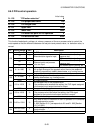
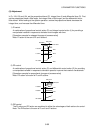
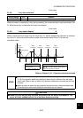
[Set point setting] [Detection value] [Manipulated variable]
variable (Hz)
Manipulated
MEMO
For the set point, process value and deviation signal, set their % equivalents.
1) When the selected feature of the set point is 0V to +5V, 0V corresponds to 0%
and +5V to 100%. When it is 0V to +10V, 0V corresponds to 0% and +10V to
100%.
2) When the process value is 4mA to 20mA, 4mA corresponds to 0% and 20mA to
100%.
3) When the deviation signal is -5V to +5V, -5V corresponds to -100%, 0V to 0%,
and +5V to 100%. When it is -10V to +10V, -10V corresponds to -100%, 0V to
0%, and +10V to 100%.
Set the Pr. 133 value when entering the set point from the operation panel.
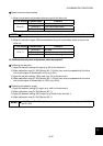
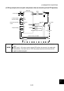
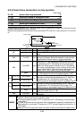
(3) Assign the used input and output signals.
Refer to: 8.4 Selection for the Control Circuit Contact Input Terminal Functions
8.7.2 Selection for the control circuit output terminal functions
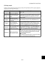
Signal Name Function
Input X14
Enter this signal to cancel PID control operation. Input of the X14 signal
stops PID action and starts normal operation.
FUP
Turns "ON" when the process value input to the terminal 4 exceeds the
Pr. 131 setting.
FDN
Turns "ON" when the process value input to the terminal 4 exceeds the
Pr. 132 setting.
Output
RL
Turns "ON" when the output display of the operation panel is forward
rotation (FWD). Turns "OFF" when the display is reverse rotation (REV) or
stop (STOP).
MEMO
Entry of multi-speed (RH, RM, RL signal) or JOG operation (JOG signal) stops PID
control and starts multi-speed operation [Section 8.3.2] or JOG operation [Section
8.6.1].
When you selected the setting of Pr. 79 = 6 (switch-over mode [Section 8.2]), you
cannot perform PID operation.