


3. WIRING
3-9
3
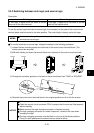
3.2.9 Wiring of the DC terminals P/+, N/-
These terminals are designed for connection of the BU brake unit or high power factor converter.
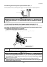
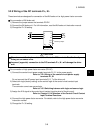
For connection of BU brake unit
1) Remove the jumper across the terminals PR-PX.
2) Connect the BU brake unit. For full information, read the BU brake unit instruction manual.
3) Change the Pr. 30 setting.
R
S
T
U
V
W
M
NFB
PR
PX
PN
P/
+
N/
-
BU brake unit
Moto
r
Remove jumper.
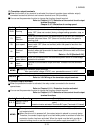
CAUTION
Do not connect the brake resistor or the like to the DC terminals P/+, N/- directly.
Doing so can cause a fire.
Incorrect (opposite) connection to the DC terminals P/+, N/- will damage the drive
unit.
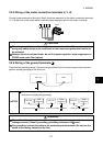
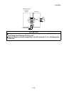
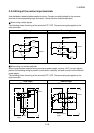
For connection of high power factor converter (FR-HC)
1) Connect the control circuit power supply terminals R1, S1 to the power supply.
Refer to: 3.2.4 Wiring of the control circuit power supply
terminals R1, S1
Do not connect the AC power input terminals R, S, T of the drive unit.
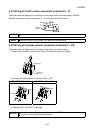
2) Select sink logic (factory setting) as the control logic of the control circuit contact input
terminals.
The converter cannot use source logic.
Refer to: 3.3.3 Switching between sink logic and source logic
3) Assign the X10 signal to the control circuit contact input terminal of the drive unit.
Refer to: Chapter 8, 8.4 Selection of the Control Circuit Contact
Input Terminal Functions
4) Connect the high power factor converter. For details, refer to the high power factor converter
instruction manual.
5) Change the Pr. 30 setting.