


8 PARAMETER FUNCTIONS
8-60
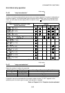
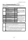
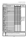
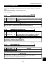
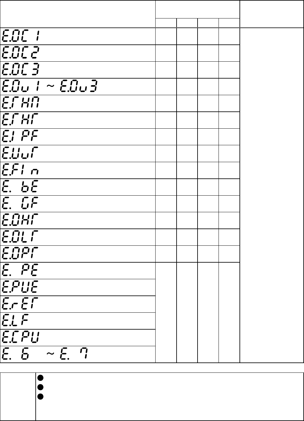
The operations of the control circuit transistor output terminals relative to the alarm codes are listed
in the following table.
Logic of Output
Terminals
Alarm Code Displayed on Operation Panel
(Actual Characters)
SU IPF OL FU
Definition of
Logic
(E. 0C1)
0001
(E. 0C2)
0010
(E. 0C3)
0011
(E. 0V1 to E. 0V3)
0100
(E. THM)
0101
(E. THT)
0110
(E. IPF)
0111
(E. UVT)
1000
(E. FIN)
1001
(E. BE)
1010
(E. GF)
1011
(E. OHT)
1100
(E. OLT)
1101
(E. OPT)
1110
(E. PE)
(E. PUE)
(E. RET)
(E. LF)
(E. CPU)
(E. 6, E. 7)
1111
Logic "0" indicates
that the transistor
output terminal is
"OFF", and logic
"1" indicates that
the transistor
output terminal is
"ON".
MEMO
Refer to "Chapter 6 Troubleshooting" for details of the alarm codes.
When this function is activated, Pr. 191 to 194 are disabled.
This function is activated for the terminals SU, IPF, OL and FU only. It cannot be
activated for the other terminals where the SU, IPF, OL and FU signals have been
selected.