


3. WIRING
3-15
3
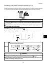
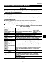
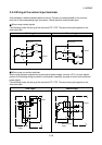
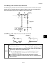
3.3.3 Switching between sink logic and source logic
Description
Sink Logic Source Logic
In this logic, a signal turns ON when a current
flows out of the input terminal.
In this logic, a signal turns ON when a current
flows into the input terminal.
To use the contact input terminals as source logic, the connector on the back of the control circuit
terminal block must be moved to the other position. The control logic is factory-set to sink logic.
MEMO
You need not change the connector position when using only the transistor output
terminals as source logic.
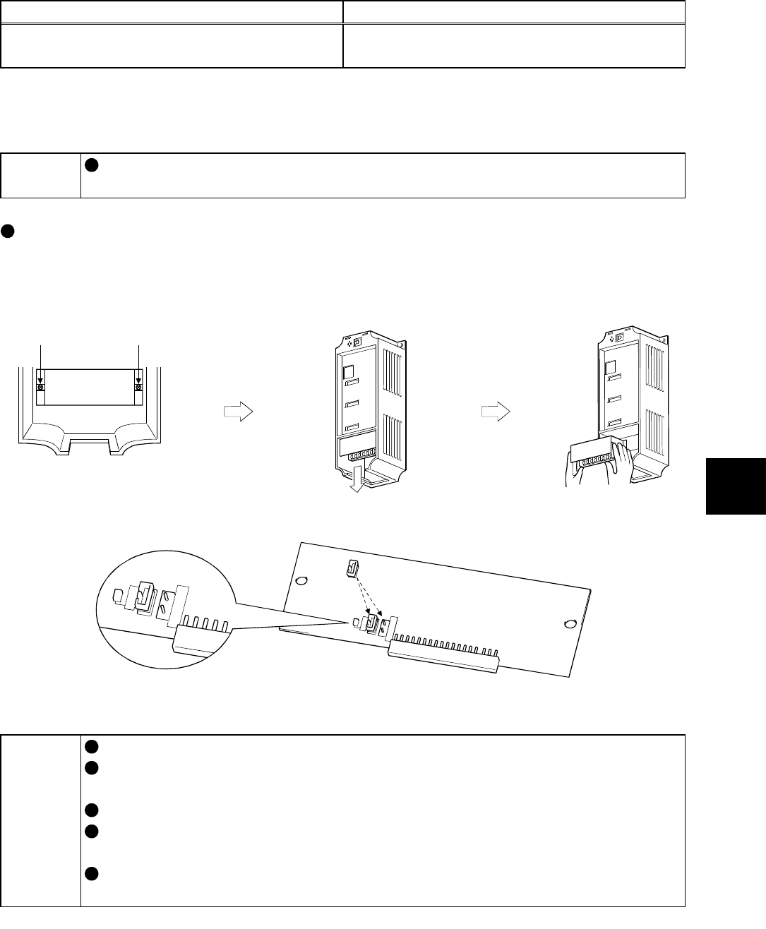
To use the terminals as source logic, change the setting in the following procedure.
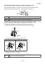
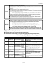
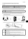
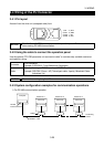
1) Loosen the two mounting screws on both ends of the control circuit terminal block. (The
screws cannot be removed.)
2) With both hands, pull down the terminal block from the back of the control circuit terminals.
Loosen. Loosen.
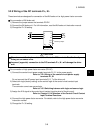
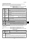
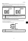
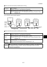
3) Change the connector position on the back of the terminal block from "SINK" to "SOURCE".
CON1
SINK
CON3
CON2
SOURCE
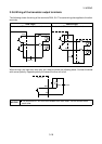
SINK
CON3
CON2
SOURCE
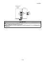
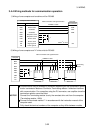
4) Reinstall the control circuit terminal block in the original position and fix it with the screws.
NOTICE
While power is on, never disconnect the control circuit terminal block.
Check the control circuit connector CON1 to ensure that the pins are fitted properly
without bending.
Make sure that the logic changing connector is inserted correctly.
The logic changing connector is a small component. Handle it with care when
changing the logic.
The logic changing connector must be fitted in only one of the above positions.
Fitting it in both positions at the same time can cause a failure.