


8 PARAMETER FUNCTIONS
8-38
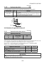
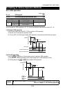
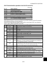
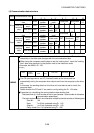
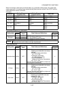
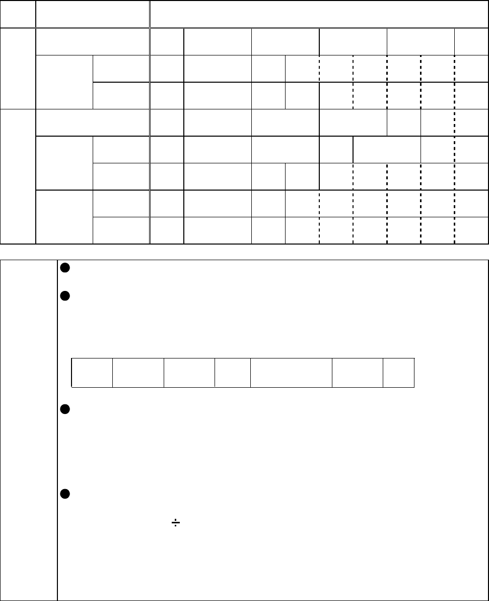
(4) Communication data structure
Number of Characters
Mode Communication Data
1 2 3 4 5 6 7 8 9 10
Computer sending
data
ENQ
Station
number
Instruction
code
Data code Sumcheck
CR
LF
Without
error
ACK
Station
number
CR
LF
Write
Drive unit
returning
data
With error NAK
Station
number
Error
code
CR
LF
Computer sending
data
ENQ
Station
number
Instruction
code
Sumcheck
CR
LF
Without
error
STX
Station
number
Data code EXT Sumcheck
CR
LF
Drive unit
sending
data
With error NAX
Station
number
Error
code
CR
LF
Without
error
ACK
Station
number
CR
LF
Read
Computer
replying
data
With error NAK
Station
number
CR
LF
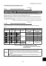
MEMO
The above format assumes that the data code has two characters. The number of
characters in the data code changes with the communication data.
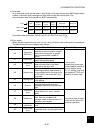
When using the computer sending data to set the "waiting time", insert the "waiting
time" data (one character) in the position next to the instruction code.
In this case, set 9999 in Pr. 123.
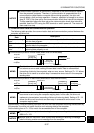
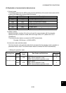
ENQ
Sumcheck
(Example)
Station
number
Instruction
code
Waiting
time
Data code
CR
LF
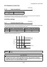
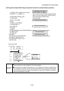
The CR (carriage return) and LF (line feed) codes at the format end are
automatically set by the computer when data is sent from the computer to the drive
unit.
In this case, the sending data from the drive unit must also be set to match the
computer data.
Select whether the CR and LF are used or not by setting the Pr. 124 value.
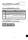
Expression for calculating the communication data sending time
Data send time (s) = total number of bits in one character
×
total number of characters
communication speed (bps)
The total number of bits in one character is equal to the total number of following bits.
Start bit: 1 bit
Data: 7 or 8 bits (selected using Pr. 119)
Stop bit: 1 or 2 bits (selected using Pr. 119)
Parity check:0 or 1 bit (selected using Pr. 120)