


6. TROUBLESHOOTING
6-15
6
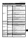
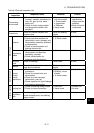
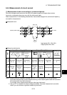
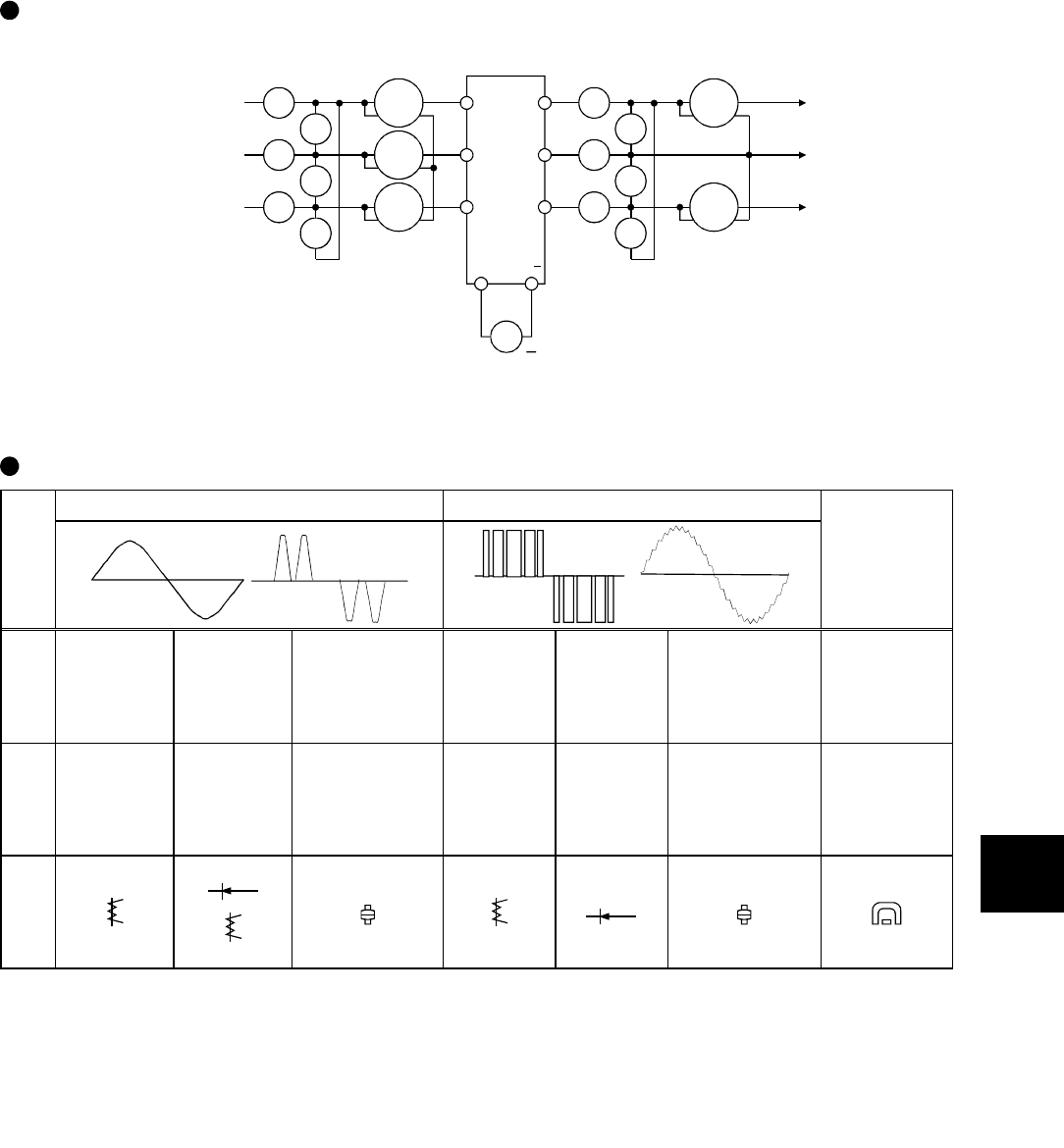
6.4.5 Measurement of circuit current
(1) Measurement of main circuit voltages, currents and powers
Since the voltages and currents on the drive unit's power supply and output sides include
harmonics, measured values may vary with the instrument types.
Make measurement in the following method when instruments designed for commercial frequency
are used for measurement.
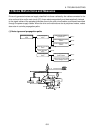
Measured circuit
Ar
As
At
Vr
Vs
Vt
W
11
W
12
W
13
Au
Av
Aw
Vu
Vv
Vw
W
21
W
22
V
R
S
T
U
V
W
P/
+
N/
+
To motor
3-phase power supply
Drive unit
Input power=W
11
+W
12
+W
13
Output power=W
21
+W
22
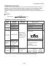
Measuring instruments
Input (Power Supply) Side Output (Motor) Side
Item
Current
waveform
Voltage
waveform
Voltage
waveform
Current
waveform
DC Circuit
P/+, N/-
Terminals
Instrument
name
Ammeter
Ar, s, t
Voltmeter
Vr, s, t
Wattmeter
W
11
,
12
,
13
Ammeter
Au, v, w
Voltmeter
Vu, v, w
Wattmeter
W
21
,
22
DC voltmeter
V
Instrument
type
Moving-
iron
Rectifier or
moving-
iron
Electrodynamic
Moving-
iron
(Note 1)
Rectifier
(Note 2)
Electrodynamic Moving-coil
Instrument
signal
Note 1. When the carrier frequency exceeds 5kHz (Pr. 72 = 3 [Section 8.5.7]), do not use the
instrument because eddy current losses occurring in the metallic parts inside the instrument
will increase and may lead to burnout.
In this case, use an approximate effective value type instrument.
2. Use an FFT to measure the output voltage accurately. Accurate measurement cannot be
made if you use a tester or general measuring instrument.