


3. WIRING
3-1
1
2
3
4
5
6
7
8
3. WIRING
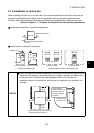
This chapter describes the wiring of the drive unit.
WARNING
Any person who is involved in the wiring of this equipment should be fully
competent to do the work. Otherwise, an electric shock or fire can occur.
Always install the unit before wiring. Otherwise, an electric shock or fire can occur.
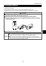
Before restarting wiring after switching power "ON", make sure that the motor is at
a stop, wait for more than 10 minutes after switching power "OFF", and confirm that
the DC voltage across the DC terminals P/+ and N/- is low enough to do wiring.
Immediately after power "OFF", the DC terminals P/+, N/- are charged with more
than 200V (residual voltage of the internal capacitor). Therefore, an electric shock
may occur.
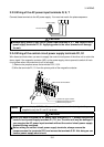
Even after power-off, the motor connection terminals U, V, W have high voltages
while the motor is running. Always start wiring after confirming that the motor has
stopped. Not doing so can cause an electric shock.
CAUTION
Take measures to prevent peripheral sensors and equipment from malfunctioning
due to electromagnetic noises. Not doing so can cause accidents.
Take measures to prevent peripheral power capacitors and generators from
overheating or being damaged due to power harmonics. Not doing so can cause a
fire.
Do not leave wire offcuts in the drive unit. Doing so can cause a fault, failure or
malfunction.
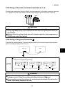
If the machine must not be restarted when power is restored after a power failure,
provide a magnetic contactor on the power supply side and also make up a
sequence which will not turn "ON" the start signal automatically when power is
restored.
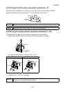
Tighten the terminal screws to the specified torque. Undertightening can cause an
inter-terminal short circuit or malfunction. Overtightening can cause the screws and
unit to be damaged, resulting in a short circuit, malfunction or the like.
When using the unit having a built-in brake resistor or using the brake resistor
(option), switch power off with the alarm signal of the unit. If you do not so, a brake
transistor failure or like may overheat the brake resistor abnormally, causing a fire.
Contents of This Chapter
Page
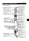
3.1 Pre-Wiring Instructions 3-3
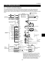
3.1.1 Terminal connection diagram............................................................. 3-3
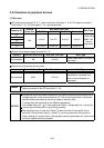
3.1.2 Noises ............................................................................................... 3-4