


3. WIRING
3-13
3
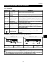
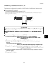
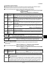
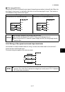
(3) Transistor output terminals
When the function of any terminal is activated, the internal transistor (open collector output)
connected across that terminal and common terminal turns ON (conducts).
You can set the parameter function to change the function of each terminal.
Refer to: Chapter 8, 8.7.2 Selection of the control circuit output
terminal functions
Chapter 8, 8.7.3 Detection of running speed
Symbol Name Description
RUN Running
ON (conducts) while the drive unit is outputting a speed command to the
motor. OFF (does not conduct) during voltage braking operation, stop, or
coasting.
FU
Speed
detection
Turns ON (conducts) when the speed output by the drive unit reaches or
exceeds the preset value. OFF (does not conduct) when the speed is
less than that.
SU Up to speed
Turns ON (conducts) when the speed output by the drive unit reaches the
preset value. OFF (does not conduct) when the speed is less than the
preset value.
OL
Overload
alarm
Turns ON (conducts) when stall prevention is activated. OFF (does not
conduct) when stall prevention is deactivated. (Minimum width of ON-time
output signal: 100ms)
Refer to : Pr. 22 [Section 8.5.6]
IPF
Instantaneous
power failure
Turns ON (conducts) when instantaneous power failure or undervoltage
protection is activated.
SE
Transistor
output
common
Common to the transistor output terminals. Isolated from the terminals
SD, 5.
MEMO
Ratings of transistor output terminals
Max. permissible voltage: 27VDC, max. permissible current: 0.1ADC
NOTICE
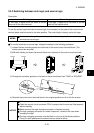
When driving a coil load, connect a diode.
Refer to: 3.3.6 Wiring of the transistor output terminals
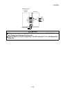
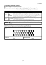
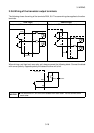
(4) Contact output terminals
When the protective function is activated, the relay contact connected to the terminal
opens/closes
Refer to: Chapter 6, 6.1.1 Protective function activated
You can set the parameter function to change the function of each terminal.
Refer to: Chapter 8, 8.7.2 Selection of the control circuit output
terminal functions
Symbol Contact Capacity Description
A, B, C
200VAC 0.3A or
30VDC 0.3A
Normal : Terminals B-C closed (Terminals A-C
open)
Protective function activated: Terminals B-C open (Terminals A-C closed)
MEMO
The response time of the contact output terminals is less than 100ms. (After drive
unit output shutoff)
When the drive unit is powered off, the contact output is placed in a normal status.
Therefore, the contact output signal is not held when power is switched off after the
protective function has been activated. When the signal must be held, provide an
external holding circuit or use the control circuit power supply terminals R1, S1.