


3. WIRING
3-20
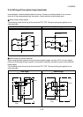
3.4 Wiring of the PU Connector
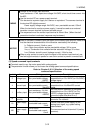
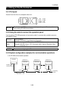
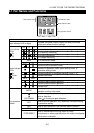
3.4.1 Pin layout
As seen from the drive unit (receptacle side) front
1) SG
2) P5S
3) RDA
4) SDB
5) SDA
6) RDB
7) SG
8) P5S
8)
to
1)
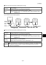
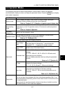
NOTICE
Pins No. 2 and 8 (P5S) provide power to the operation panel. Do not use them
when making RS-485 communication.
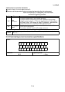
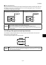
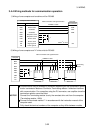
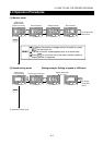
3.4.2 Using the cable to connect the operation panel
Use the optional "FR-CB2 parameter unit connection cable" or commercially available connector
and cable for wiring.
Connector
RJ45 connector
Example: 5-554720-3, Tyco Electronics Corporation
Cable
Cable conforming to EIA568 (such as 10BASE-T cable)
Example: SGLPEV 0.5mm
×
4P (Twiced pair cable, 4 pairs), Mitsubishi Cable
Industries, Ltd.
NOTICE
The maximum wiring length is 20m.
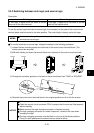
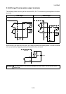
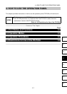
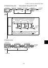
3.4.3 System configuration examples for communication operations
1) For RS-485 communication operation
Computer
RS-485
interface/terminal
10BASE-T cable
Station No. 1 Station No. 2 Station No. n
Drive unit
PU connector
Splitter
Terminating
resistor
Drive unit
PU connector
Drive unit
PU connector