


2. INSTALLATION
2-4
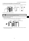
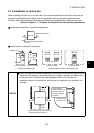
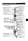
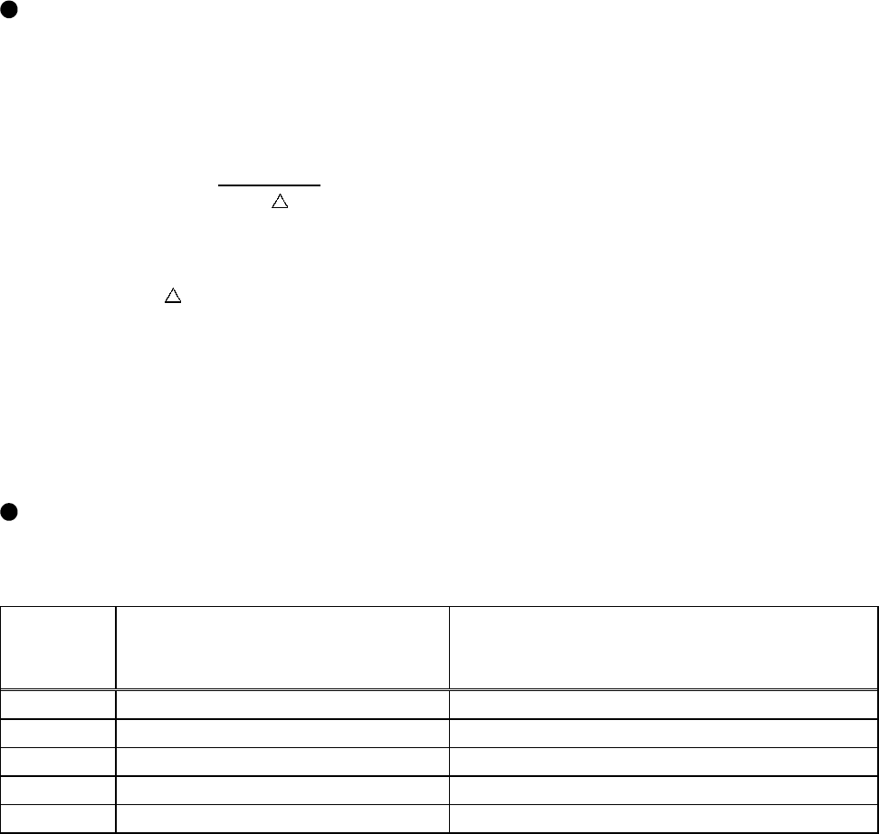
Installation in enclosed control box
The following is the relationship between the internal temperature rise and heat dissipation area of
an enclosed control box (hereafter referred to as the enclosure) which accommodates the drive
unit.
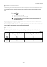
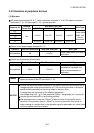
P
A =
K
•
T
A: Heat dissipation area (m
2
)
P: All losses produced in enclosure (W)
T: Difference between enclosure inside and outside-air temperatures (
°
C)
K: Heat dissipation factor
The heat dissipation area A does not include the area in contact with a structures which interfere
with heat dissipation, e.g. floor and walls.
The heat dissipation factor K used is normally 5 to 6, which depends on the enclosure structure, the
layout of parts in the enclosure, and the outside-air temperature.
Produced losses
The following table indicates the losses produced during rated load operation of the drive unit.
Unit (W)
Capacity
Drive Unit-Produced Loss during
Continuous Rated Load
Operation
Loss Produced in Enclosure when Drive
Unit Heat Sink Is Placed Outside of
Enclosure
0.5K 55
1.0K 70
1.5K 110 33
2.0K 150 45
3.5K 230 69