9 - 41
– +
ELEC
SIGNAL SYSTEM
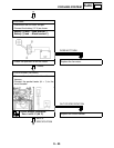
C0NTINUITY
CORRECT
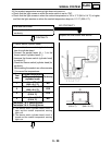
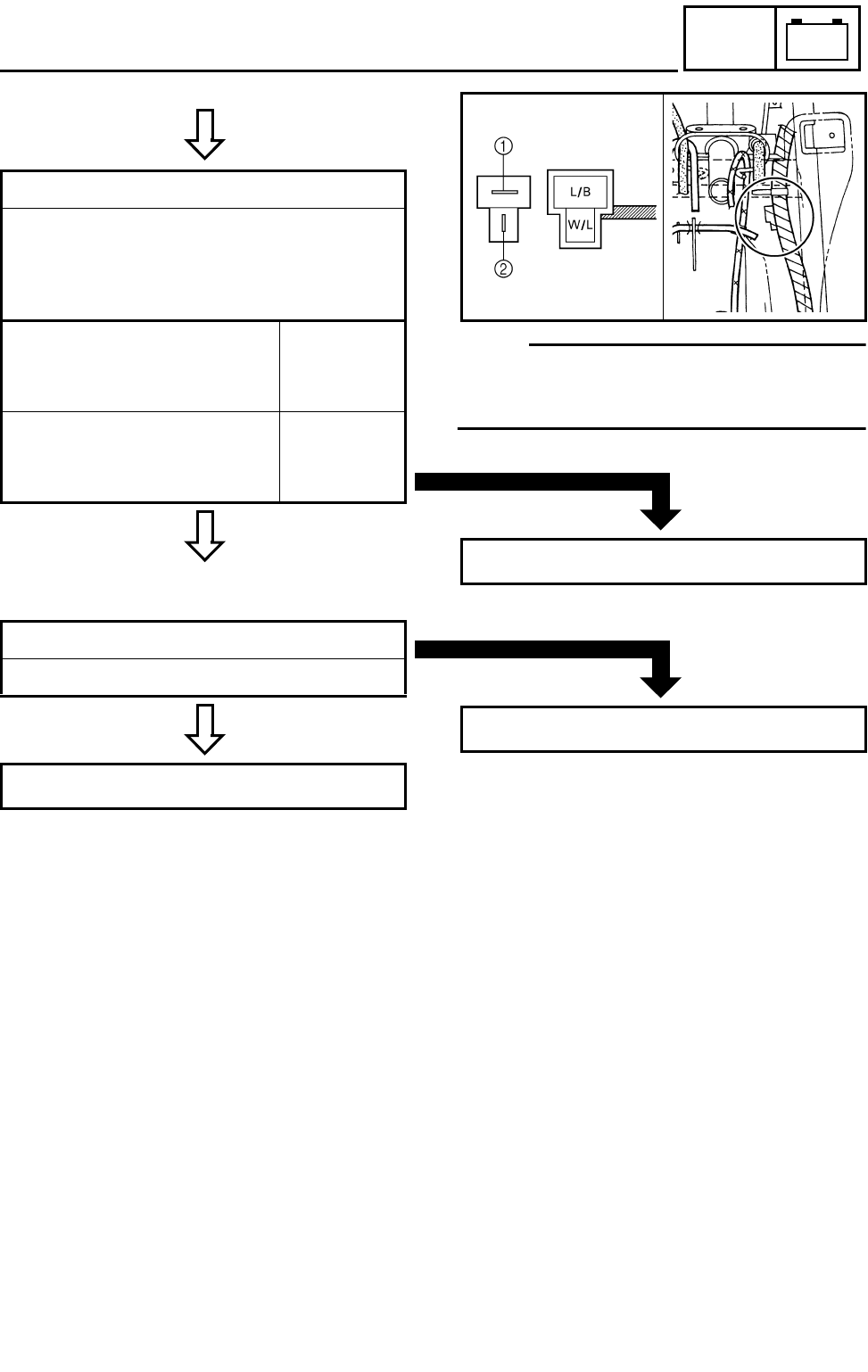
4.Diode
●
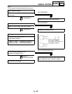
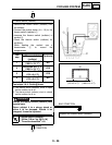
Remove the diode from the coupler.
●
Connect the pocket tester (Ω × 1) to the
diode terminals as shown.
●
Check the diode for continuity as follows.
Tester (+) lead
→
Blue/Black terminal
1
Tester (–) lead
→
White/Blue terminal
2
Continuity
Tester (+) lead
→
White/Blue terminal
2
Tester (–) lead
→
Blue/Black terminal
1
No
continuity
*
N
OTE:
When you switch the tester’s positive and
negative probes, the readings in the left chart
will be reversed.
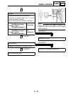
INCORRECT
Replace the diode.
CORRECT
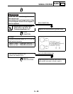
5.Start switch
Refer to “CHECKING THE SWITCHES”.
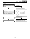
This circuit is not faulty.
INCORRECT
Replace the handlebar switch (left).


