


ENGINE
3.42
5. Using valve guide driver, drive guides out of the
cylinder head from the combustion chamber side.
Be careful not to damage guide bore or valve seat
when removing guides.
6. Place cylinder head on cylinder head table.
NOTE: Be sure cylinder head is still at 212q F
(100q C) before installing new guides.
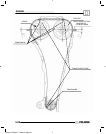
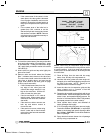
7. Place a new guide in the valve guide installation
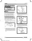
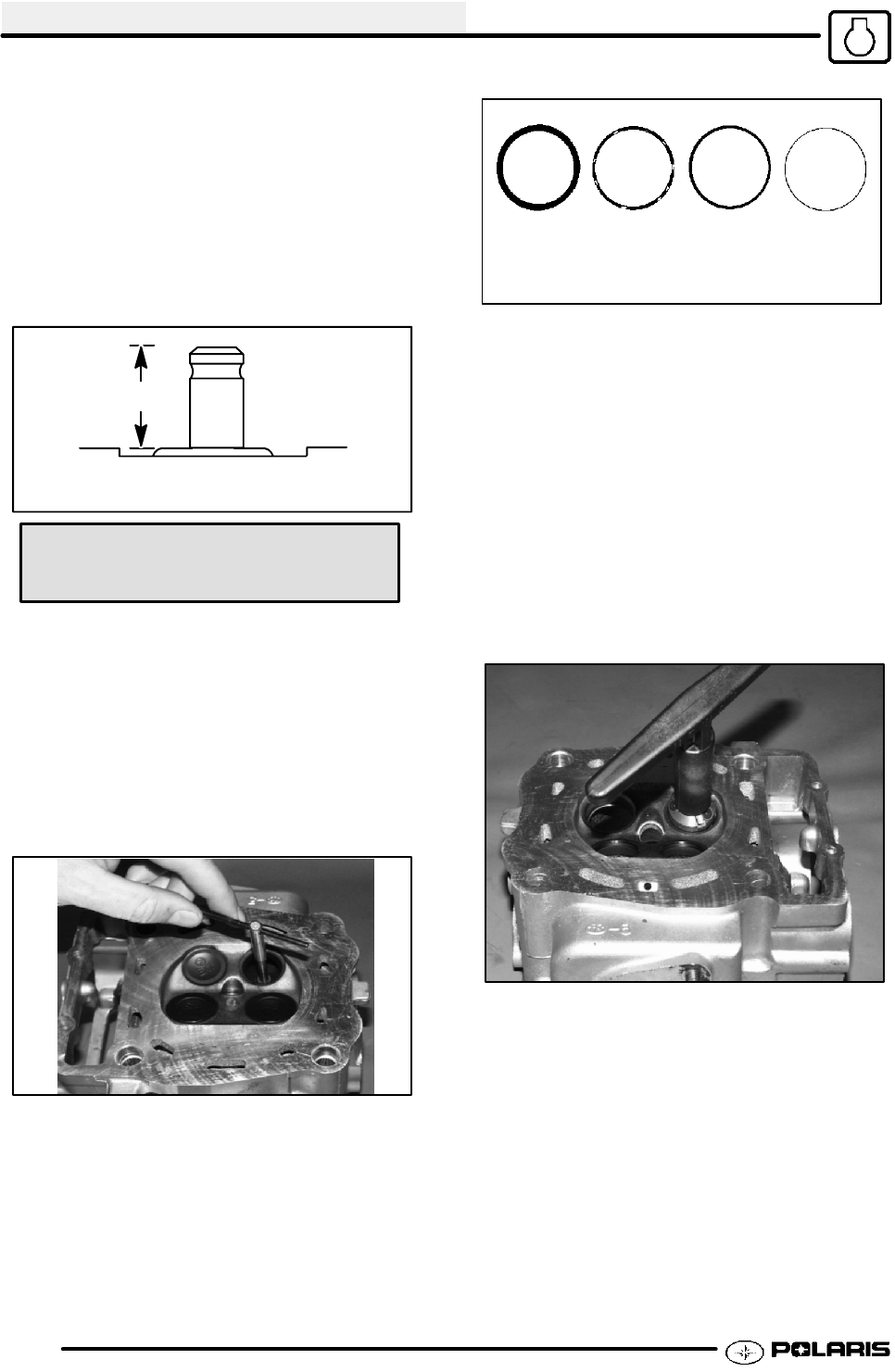
tool and press guide in to proper depth. Check
height of each guide above the cylinder head (A).
A
Valve Guide Installed Height
Valve Guide Height:
.689-.709I (17.5-18.0 mm)
NOTE: The guide can also be inserted to the
proper depth using a driver. Inspect the guide
closely for cracks or damage if a driver is used.
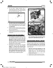
8. Allow the cylinder head to cool to room
temperature. Apply cutting oil to the reamer.
Guides should be reamed from the valve spring
side of the cylinder head. Ream each guide to
size by turning the reamer clockwise continually.
Continue to rotate reamer clockwise during
removal of the tool.
9. Clean guides thoroughly with hot soapy water and
a nylon brush. Rinse and dry with compressed
air. Apply clean engine oil to guides.
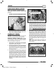
VALVE SEAT RECONDITIONING
Follow the manufacturers instructions provided with
the Valve Seat Reconditioning Kit (PN 2200634).
Abrasive stone seat reconditioning equipment can
also be used. Keep all valves in order with their
respective seat.
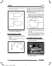
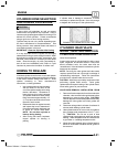
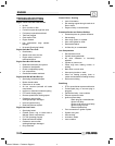
Too
Wide
Uneven
Good
Too
Narrow
Valve seat wear patterns
NOTE: Valve seat width and point of contact on the
valve face is very important for proper sealing. The
valve must contact the valve seat over the entire
circumference of the seat, and the seat must be the
proper width all the way around. If the seat is uneven,
compression leakage will result. If the seat is too
wide, seat pressure is reduced, causing carbon
accumulation and possible compression loss. If the
seat is too narrow, heat transfer from valve to seat is
reduced and the valve may overheat and warp,
resulting in burnt valves.
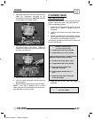
10. Install pilot into valve guide.
11. Apply cutting oil to valve seat and cutter.
12. Place 46q cutter on the pilot and make a light cut.
13. Inspect the cut area of the seat:
G If the contact area is less than 75% of the
circumference of the seat, rotate the pilot
180q and make another light cut.
G If the cutter now contacts the uncut
portion of the seat, check the pilot. Look
for burrs, nicks, or runout. If the pilot is
bent it must be replaced.
Enfocus Software - Customer Support