


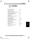

ELECTRICAL
7.6
--+
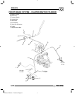
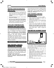
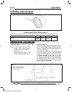
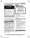
Current Draw Inspection
Key Off
YTX9--BS
Ill. 1
Current Draw - Key Off:
Maximum of .01 DCA (10 mA)
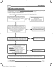
CHARGING SYSTEM “BREAK
EVEN”
TEST
CAUTION: Do not allow the battery cable or
ammeter to become disconnected with the
engine running. Follow the steps below as
outlined to reduce the chance of damage to
electrical components.
W ARNING: Never start the engine with the ammeter
connected in series. Damage to the meter or meter
fuse will result. Do not run test for extended period of
time. Do not run test with high amperage accessories.
The “break even” point of the charging system is the
point at which the alternator overcomes all system
loads (lights, etc.) and begins to charge the battery.
Depending on battery condition and system load, the
break even point may vary slightly. The battery should
be fully charged before performing this test.
1. Connect a tachometer according to manufacturer’s
instructions.
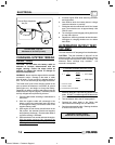
2. With the negative cable still connected to the
battery, connect one meter lead (set to DC amps)
to the negative battery post and the other to the
negative battery cable
3. With engine off and the key and kill switch in the
ON position, the ammeter should read negative
amps (battery discharge). Reverse meter leads if
a positive reading is indicated.
4. Shift transmission into neutral and start the engine.
With the engine running at idle, dis connect th
e
negative cable from the battery post withou
t
disturbing the meter leads.
Observe meter readings
5. Increase engine RPM while observing ammeter
and tachometer.
6. Note RPM at which the battery starts to charge
(ammeter indication is positive).
7. With lights and other electrical load off, the “break
even” point should occur at approximately 1500
RPMorlower.
8. Turn the lights on and engage parking brake lock
to keep brake light on.
9. Repeat test, observing ammeter and tachometer.
With lights on, charging should occur at or below
2000 RPM.
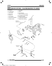
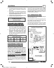
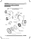
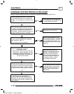
ALTERNATOR OUTPUT TEST
(AC
AMP)
This test measures AC amperage from the alternator.
CAUTION: This test simulates a “full load” on the
alternator at idle. Do not increase idle RPM or perform
this test longer than required to obtain a reading. The
alternator stator windings may overheat. 3--5
seconds is acceptable.
To Calculate Available Alternator Output
250W
12V
= 20.8 Amps
I
=
P
E
I = Current in Amps
P=PowerinWatts
E = Electromotive Force (Volts)
200W
12V
=16.7Amps
1. Maximum alternator output will be indicated on the
meter. DO NOT increase engine RPM above idle
.
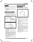
2. Place the red lead on the tester in the 10A jack.
3. Turn the selector dial to the AC amps position.
4. Connect the meter leads to the Yellow and
Yellow/Red wires leading from the alternator.
5. Start the engine and let it idle. Reading should be
a minimum of 5A/AC at idle.
Alternator Current Output:
Minimum of 5 AC Amps at Idle
Enfocus Software - Customer Support