


BODY / STEERING / SUSPENSION
5.41
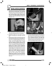
78. Push the IFP further into the reservoir. As you do
this, the shaft and bearing assembly should rise
until the bearing assembly engages with the wire
retaining ring inside the body tube. Remove the
IFP depth setting tool by rotating it 90 degrees.
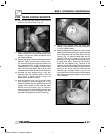
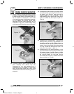
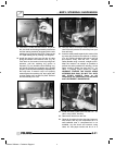
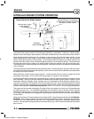
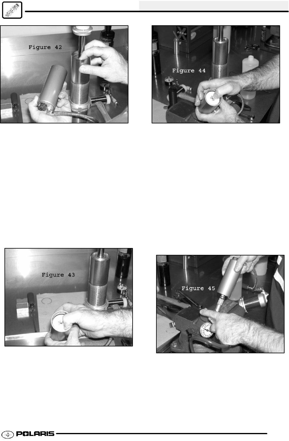
79. Install the reservoir end cap with the air valve
facing the outside of the reservoir tube. (Fig. 43)
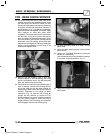
Push down on the reservoir end cap using even
pressure, until the retaining ring groove is
exposed. (Fig. 44) Install the wire retaining ring,
and check to make sure retaining ring is seated
properly. Push the shaft assembly completely into
the body tube. If reservoir cap is not properly
seated against the retaining clip, tap it gently with
a rubber mallet until it snaps into place. Remove
shock assembly from vise.
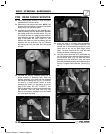
80. Securely clamp Fox Nitrogen Safety Needle in the
vise. Be sure to point the air valve away from your
face and body.
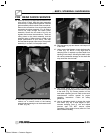
81. Insert the safety needle squarely into center of the
air valve and pressurize the reservoir to 300psi.
(Fig. 45) Continue charging with gas as you pull
the reservoir away from the Foxt Nitrogen
Safety Needle using a smooth, straight motion.
Keep the reservoir as straight as possible to
prevent the safety needle from bending. As the
safety needle is pulled free from the Foxt air
valve, a popping sound should be heard.
W ARNING: CHARGE THE SHOCK USING
NITROGEN GAS ONLY. DO NOT FILL WITH
ANY OTHER GASSES. Doing so will
compromise the performance of the shock
and is EXTREMELY DANGEROUS!
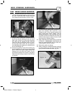
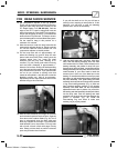
82. Install the button--head screw into the Foxt air
valve, using a 3/32” Hex Key.
83. Remove the shock from the vise.
84. Clean all oil residue from the shock and reservoir
with solvent, and dry with compressed air in a
well--ventilated area. If compressed air is not
available, dry the shock and reservoir using
clean, lint free paper towels and let sit in a
Enfocus Software - Customer Support