


ENGINE
3.14
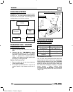
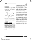
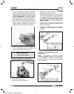
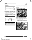
4. To retract the plunger, rotate the special tool
clockwise while holding the tensioner stationary.
You may also hold the special tool stationary and
rotate the tensioner assembly counter--clockwise
if desired. I MPORTANT: Do not grind edges of
key flange into tensioner to prevent damage to the
tool or locking guides during plunger retraction.
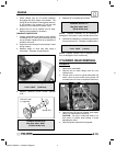
5. Once retraction is complete, lock the tool into the
tensioner guides. This holds the spring and
plunger in place for reassembly. Use caution not
to disturb the tool during tensioner installation.
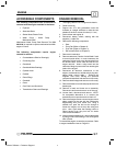
6. Reinstall the tensioner assembly, torquing the
bolts to specification (Pg 3.2). Remove the
special tool and replace the tensioner cap.
Tensioner Bolt Torque:
6.6-8.1 ft lbs (9-11 Nm)
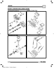
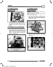
CAMSHAFT REMOVAL AND INSPECTION
1. Remove the valve cover.
2. Remove the tensioner assembly.
3. Remove the 8 bolts securing the cam tower
assembly and remove the cover.
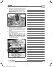
4. To free the cam assembly, lift one cam assembly
and slightly rotate it while removing the chain from
the cam gear. Repeat this procedure for the other
cam. NOTE: Do not allow cam chain to drop
into the engine if no other disassembly is
being performed.
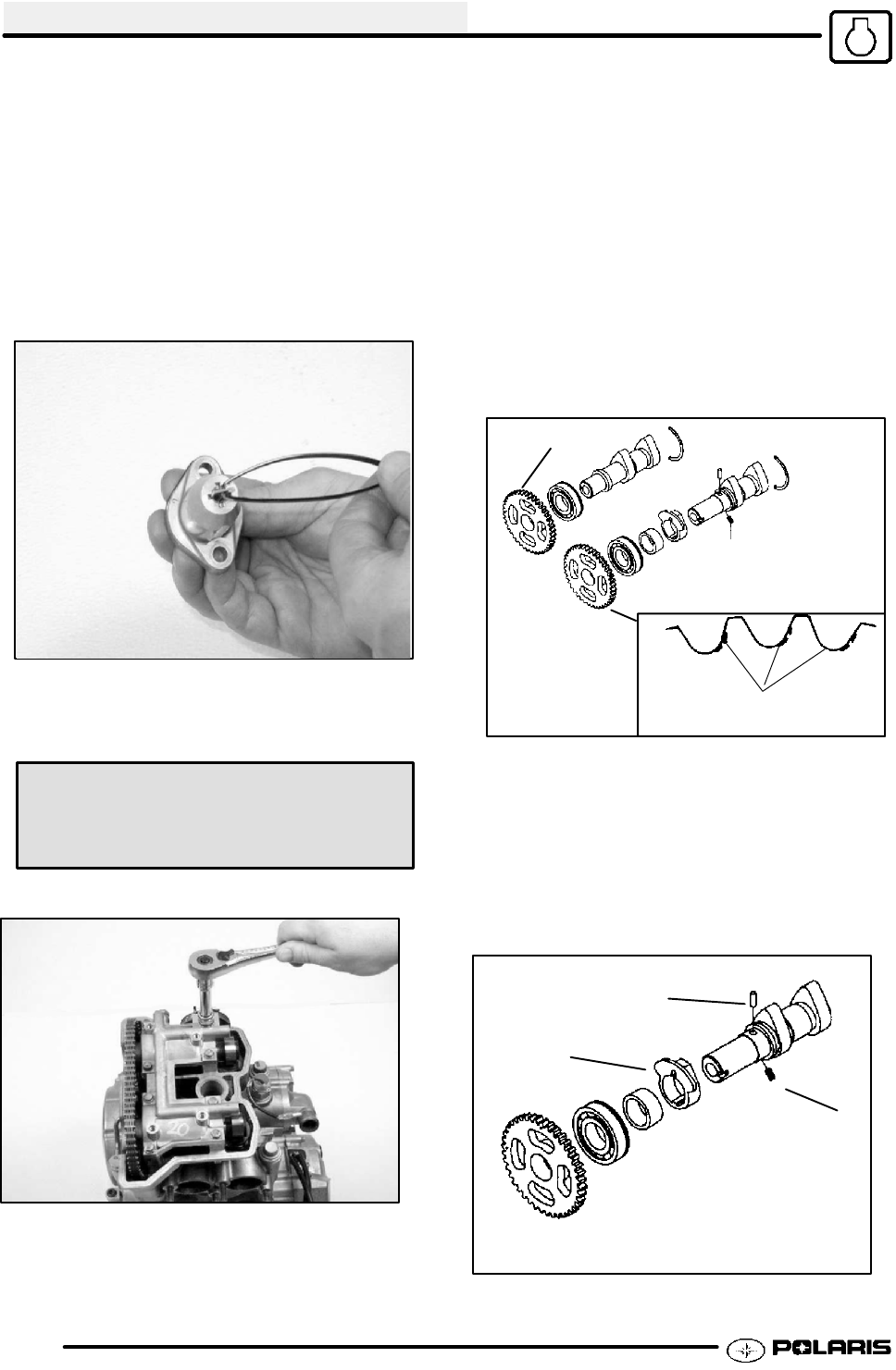
5. Use a device to secure the cam chain, such as
mechanic’s wire or nylon line, to prevent it from
falling into the engine.
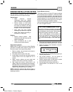
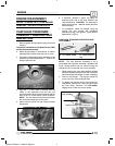
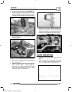
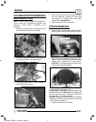
6. Inspect cam sprocket teeth for wear or damage.
If damage is found, replace the camshaft
assembly.
Inspect for Areas of Tooth
Wear or Damage
Sprocket Teeth
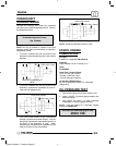
AUTOMATIC COMPRESSION RELEASE
INSPECTION
NOTE: The automatic compression release
mechanism cannot be serviced. The components
are not replaceable. Replace the camshaft as an
assembly if any part of the compression release is
worn or damaged.
A
B
C
Note: Cam and compression--release
are an assembly and not serviceable
Enfocus Software - Customer Support