


ENGINE
3.38
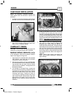
CAM CHAIN INSTALLATION
NOTE: The camshafts, crankshaft sprocket and
clutch basket must be removed to perform this
procedure.
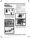
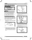
1. Install the cam chain by dropping it down through
the chain room and over the crankshaft sprocket.
B
2. Use a suitable device to hold the chain in place to
keep it from dropping through the chain room,
such as wire or a hammer handle.
CAMSHAFT TIMING
CAUTION: Serious engine damage will result if the
camshaft is not properly timed to the crankshaft.
IMPORTANT CAMSHAFT TIMING NOTE: The Top
Dead Center (TDC) mark is used to time the camshaft
to the crankshaft. Follow the procedures outlined.
Refer to the diagram on Page 3.40.
1. Apply engine oil or assembly lube to the camshaft
main journals, cam lobes and the automatic
compression release mechanism.
2. Place the thrust washer onto the crankshaft with
the chamfered side inward. Install the crankshaft
cam sprocket onto the shaft. Note the double
spline for ease of installation. The alignment mark
should face outward.
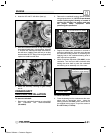
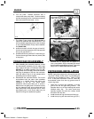
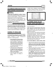
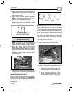
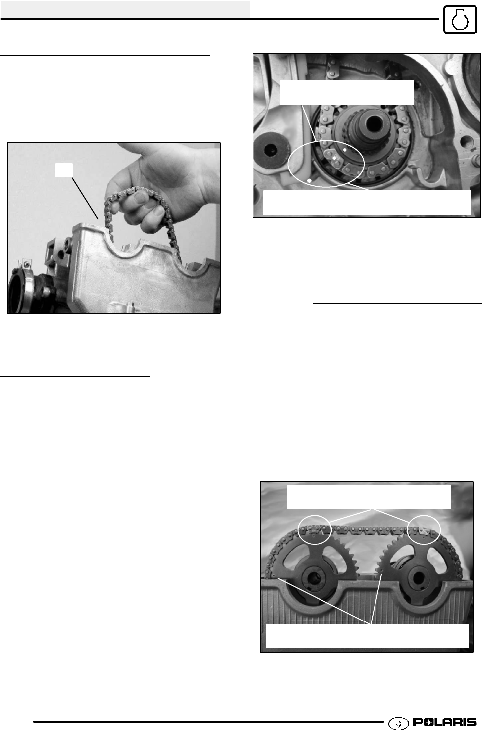
3. If not already at Top Dead Center, Loosely hold
the cam chain and rotate the crankshaft until the
crankshaft cam sprocket timing mark is aligned
with the Top Dead Center (TDC) mark on the
crankcase (see photo). Position the chain for
correct timing by aligning the bottom cam timing
mark with the brass colored bottom chain link.
Keep tension on the chain so as to not lose chain
alignment at the crankshaft sprocket during cam
installation.
Align sprocket timing mark
and brass colored chain link
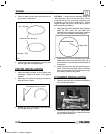
Align brass colored chainlink and sprocket
marks with Top Dead Center (TDC) mark
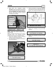
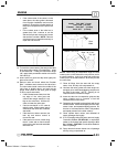
4. Install the camshafts one at a time. First, install
the exhaust cam by looping the chain over the
cam gear. At the same time, position the cam chain
for correct timing by aligning the brass colored chain
link with the 12 o’clock dot on the cam sprocket. The
sprocket secondary mark should be at the 9 o’clock
position. Keep t ension on the chain so as to no
t
lose chain alignment at the crankshaft sprocket.
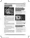
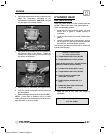
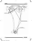
5. Next, install the intake cam, positioning the upper
cam chain for correct timing by aligning the
remaining brass colored chain link with the 12
o’clock dot on the cam sprocket. Timing is in phase
when all three brass colored cam chain links align
with all three sprocket timing marks and the
secondary cam gear marks are at approximately
the 9 o’clock position, with the exhaust cam timing
mark slightly advanced. Refer to the diagram on
Page 3.40
NOTE: Failure to align marks in this fashion will
cause valve--to--piston interference, resulting in
engine damage
Align 12 o’clock timing marks and
brass colored chain links as shown
9 o’clock timing marks approximate position
Note the exhaust cam is slightly advanced
Enfocus Software - Customer Support