


ELECTRICAL
7.5
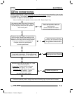
IGNITION SYSTEM
TROUBLESHOOTING
No Spark, Weak or Inte rmittent Spark
G No12 volt power or ground to CDI
G Spark plug gap incorrect
G Fouled spark plug
G Faulty spark plug cap or poor
connection to high tension lead
G Related wiring loose, disconnected,
shorted, or corroded
G Engine Stop switch or ignition
switch faulty
G ETC switch misadjusted or faulty
G Poor ignition coil ground (e.g. coil
mount loose or corroded)
G Faulty stator (measure resistance
of all ignition related windings)
G Incorrect wiring (inspect color
coding in connectors etc)
G Faulty ignition coil winding
(measure resistance of primary and
secondary)
G Worn magneto (RH) end
Crankshaft bearings
G Sheared flywheel key
G Flywheel loose or damaged
G Excessive crankshaft runout on
magneto (RH) end - should not
exceed .005s
G Faulty CDI module
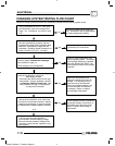
CRANKING OUTPUT TEST
WITH PEAK
READING
VOL
TMETER
The following peak voltage tests will measure the
amount of output directly from each component.
A
peak reading voltmeter must be used to perform
the
tests
. A variety of peak reading adaptors are
commercially available for use with the Fluket 77
Digital Multimeter (PV--43568), which will allow peak
voltage tests to be performed accurately. Follow the
directions provided with the adaptor. All
measurements are indicated in DC Volts. Readings
obtained without a peak reading adaptor will be
significantly different.
Test output from the CDI and pulse (trigger) coil and
compare to the table. The following measurements
are obtained when cranking the engine with the
electric starter, spark plug installed. The starter
system must be in good condition and the battery fully
charged.
200 Watt 4 Stroke DC/CDI Ignition
Test
Connect
Meter Wires
To:
Reading
(Without Pea k
Reading V olt
meter)
Pulse (Trigger) White/Red
and White
3.3 DCV
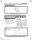
CDI OUT PUT TEST USING
PEAK READING ADAPT
OR
Re-connect all CDI wires to stator wires. Disconnect
CDI module wire from ignition coil primary terminal.
Connect one meter lead to engine ground and the
other to the ignition coil primary wire leading from the
CDI module. Set meter to read DC Volts. Crank
engine and check output of CDI wire to coil.
Reconnect CDI wire to coil.
Output w/ Peak output tester
130 DCV
Average Output w/ Digital Voltmeter
20 DCV
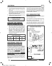
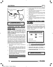
CURRENT DRAW - KEY OFF
CAUTION: Do not connect or disconnect the battery
cable or ammeter with the engine running. Damage
will occur to electrical components.
Connect an ammeter in series with the negative
battery cable. Check for current draw with the key off.
If the draw is excessive, loads should be
disconnected from the system one by one until the
draw is eliminated. Check component wiring as well
as the component for partial shorts to ground to
eliminate the draw.
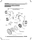
Refer to Illustration 1 on the next page.
Enfocus Software - Customer Support