ENGINE
3.31
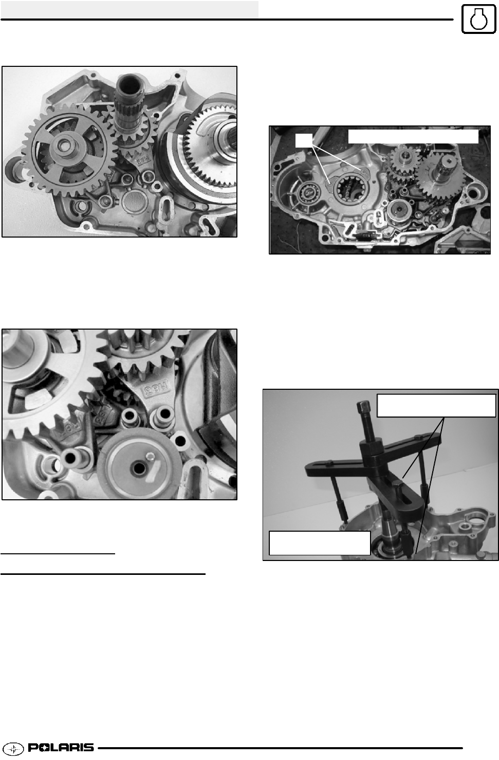
2. Insert the “M” and R” shift forks (face up).
3. Insert and rotate the shift drum to align the loctating
pin at approximately the 1 o’clock position. Align the
“L” shift fork first, then align the other shift forks into
the shift drum, installing each shift fork pin as they
are assembled. NOTE: lifting of fork and gear will be
required to install into shift drum.
4. Rotate the assembly, checking for gear binding
and fit.
CRANKSHAFT
REMOVAL/INSTALLA
TION
To remove crankshaft:
1. Remove the crankshaft retaining nut using MAG
End Crankshaft Nut Remover/Installer
(PA--46076).
2. Remove the crankshaft bearing retainer screws
using a impact driver. (A). NOTE: S crew threads
contain locking agent. Heating of screws is
required for removal. Use caution and wear
the proper safety equipment while
performing this procedure.
A
PTO side shown for clarity
3. Support the stator side crankcase in a stand to
press the crankshaft out. Use care not to damage
the crankcase mating surface or connecting rod.
Applying heat to the crankcase bearing area to
ease removal is acceptable.
4. Attach Crankcase Separator (PA--46087)tothe
casehalve. Turn the inner shaft clockwise while
holding the outer shaft to press the crankshaft
and bearing as an assembly out of the case.
Verify that all bolts are fully
threaded to avoid damage
Crankcase Separator
Tool PA--46087
To install crankshaft:
5. Press the bearing into the crankcase at the outer
edges with an appropriate driver. Insert the
bearing retainers and new screws, which have a
pre--applied locking agent. Torque the screws to
8.1-9.6 Ft Lbs.(1 1-13 Nm).
Enfocus Software - Customer Support


