


ENGINE
3.15
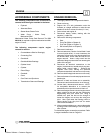
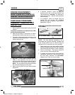
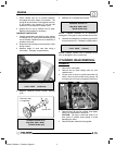
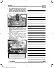
1. Check release cam (A) for smooth operation
throughout the entire range of movement. The
spring (B) should hold the cam against the stop.
In this position, the actuator (C) will be held
outward in the compression release mode.
2. Inspect lobe on end of release cam for wear.
Replace cam assembly if necessary.
CAMSHAFT INSPECTION
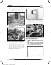
1. Visually inspect each cam lobe for wear, chafing
or damage. NOTE: cams, gears and bearings are
not serviceable. Replace cam as an assembly if
problems are found.
2. Inspect the cam bearings for excess play or noise
during rotation.
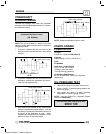
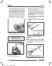
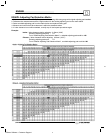
3. Measure height of each cam lobe using a
micrometer. Compare to specifications.
Camshaft Lobe Height :
Limit: 1.6555I (42.05 mm)
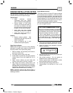
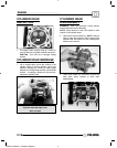
4. Measure camshaft journal outside diameter
(O.D.)
Journal O.D.
Check for wear
or roughness
Camshaft Journal O.D.:
Mag End: .9821--.9828I
(24.946--24.963 mm)
5. Measure ID of camshaft journal bore.
Camshaft Journal I.D.:
Mag End: .9842--.9851I
(25.00--25.021 mm)
NOTE: Replace camshaft as an assembly if
damaged or if any part is worn past the service limit.
6. Calculate oil clearance by subtracting journal OD
from journal bore ID. Compare to specifications.
Camshaft Oil Clearance:
Limit: .0039I (.10 mm)
NOTE: Replace cylinder head if camshaft journal
bore is damaged or worn excessively.
CYLINDER HE AD REMOVAL
ES50PL
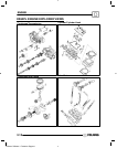
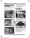
1. Remove the cam shafts.
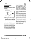
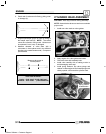
2. Remove the two 8mm flange bolts (A) from
cylinder head.
3. Loosen each of the four cylinder head bolts (B)
with a 14mm 12--point socket, turning evenly 1/8
turn each time in a criss-cross pattern until loose.
B
A
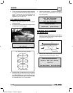
4. Remove bolts (B) and tap cylinder head lightly
with a soft--face hammer until loose.
CAUTION: Tap only in reinforced areas or on
thick parts of cylinder head casting to avoid
damaging the head.
5. Remove cylinder head and head gasket.
Enfocus Software - Customer Support