


ENGINE
3.22
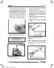
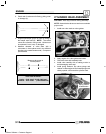
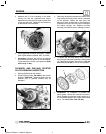
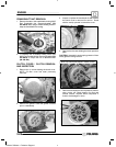
5. The oil control ring is a three piece design consisting
of a top and bottom steel rail and center expander
section. Remove the top rail first followed by the
bottom rail, then remove the expander. For
installation, refer to Page 3.35.
CYLINDER INSPECTION
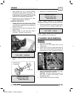
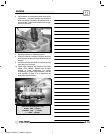
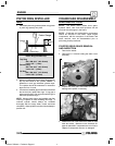
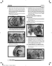
1. Remove all gasket material from the cylinder
sealing surfaces.
2. Inspect the top of the cylinder for warpage using a
straight edge and feeler gauge.
Cylinder Warpage:
.002s (.05 mm)
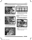
3. Inspect cylinder for wear, scratches, or damage.
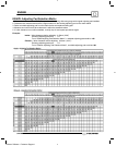
1/2s Down From Top of Cylinder
1/2s Up From Bottom
X
X
Y
Y
X
Y
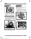
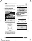
4. Inspect cylinder for taper and out of round with a
telescoping gauge or a dial bore gauge. Measure
in two different directions, front to back and side to
side, on three different levels (1/2s down from top,
in the middle, and 1/2s up from bottom).
5. Record measurements. If cylinder is tapered or
out of round beyond specification, the cylinder
must be replaced.
Cylinder Taper
Limit: .002I (.05 mm) Max.
Cylinder Out of Round
Limit: .002I (.05 mm) Max.
Standard Bore Size:
3.9055-3.9062I (99.20-99.22mm)
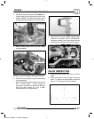
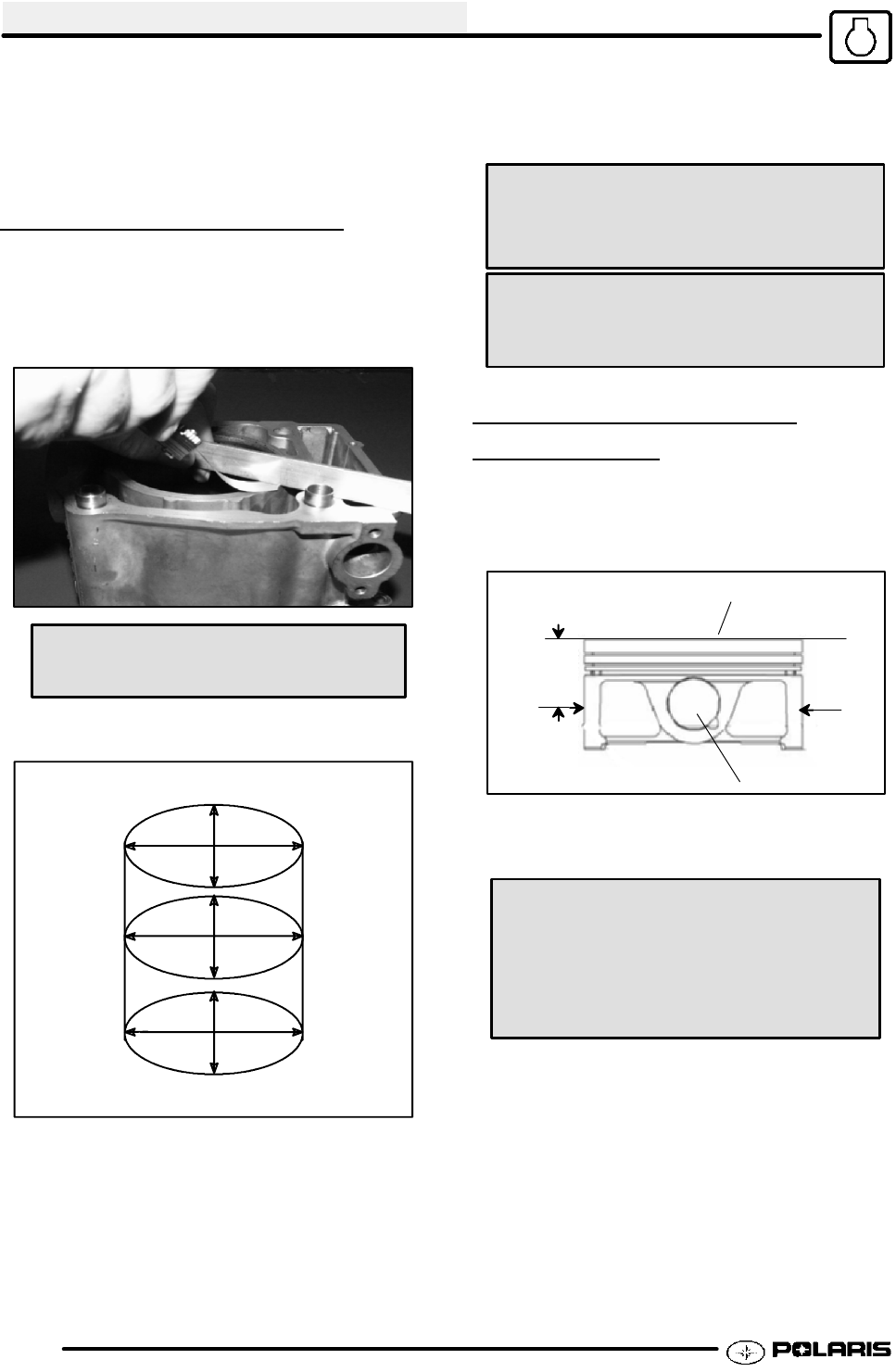
PISTON-TO-CYLINDER
CLEARANCE
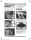
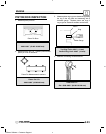
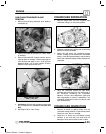
1. Measure piston outside diameter at a point 40 mm
down from the top of the piston at a right angle to
the direction of the piston pin.
40 mm
Piston
Piston Pin
2. Subtract this measurement from the maximum
cylinder measurement obtained in Step 5.
Piston to Cylinder Clearance
Std: 0018 -- .0025I (.046 -- .065 mm)
Piston O.D.:
Std: 3.9037-3.9040I (99.155-99.170mm)
Enfocus Software - Customer Support