ENGINE
3.32
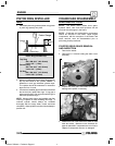
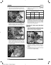
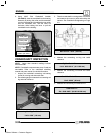
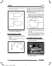
6. Using MAG End Crankshaft Installer
(PA--46077), draw the crankshaft into the bearing
assembly by sliding the collar and thrustwasher
over the crankshaft end, threading the inner puller
onto the crankshaft end. Turn the outer nut
clockwise while holding the inner to pull the
crankshaft into the bearing.
MAG End Crankshaft
Installer (PA--46077)
Collar
Thrust Washer
Inner puller
Outer puller
CRANKSHAFT INSPECTION
NOTE: Larger than standard readings indicate
excessive wear.
NOTE: Crankshaft components are press--fit and are
serviceable. Refer to the crankshaft rebuilding
manual and parts manual for rebuild information.
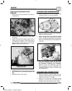
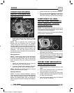
1. Inspect the crankshaft connecting rod bearing
journal for scoring and abnormal wear.
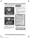
2. Use a feeler gauge to measure the connecting rod
big end side clearance.
Connecting Rod Big End Side Clearance:
Limit: .0256I (.65 mm)
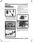
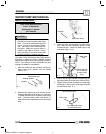
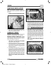
3. Place the crankshaft in a truing stand or V-blocks
and measure the runout on both ends with a dial
indicator. See Crankshaft Straightening on Page
3.9.
Max Runout: .0012s (.03 mm)
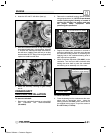
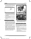
4. Measure the connecting rod big end radial
clearance.
Big End Radial Clearance:
Limit: .0004-.0015I (.01 1-.038 mm)
5. Measure the connecting rod small end radial
clearance.
Small End Radial Clearance:
Limit: .0020I (.05 mm)
6. Measure the connecting rod small end I.D.
SmallEndI.D.:
Std: .9058-.9063I (23.007-23.020 mm)
Enfocus Software - Customer Support


