ELECTRICAL
7.4
6. Turn ignition key and engine stop switch to “RUN”
position. Read the current draw on ammeter with
fan running.
7. During start--up, the amperage should peak then
decline rapidly. If the motor continues to draw
more amperage than the fan circuit breaker rating
during start--up, replace the motor.
8. If the fan motor draws more than 6.5 Amps during
continual running, replace the motor.
Fan Motor Current Draw:
Less Than 6.5 Amps
COOLANT FAN CONTROL
SWITCH OPERATION
TEST
1. Place switch in a liquid bath and submerse it to the
base of the threads. Do not allow threads to
contact container or inaccurate reading will result.
2. Heat the liquid slowly and monitor the
temperature with a thermometer or Fluket meter
pyrometer. The switch should be closed
(conductive) at the “ON” temperature indicated in
the chart, and stay conductive until the “OFF”
temperature is reached.
REFER TO PARTS MANUAL FOR F AN
SWITCH APPLICATION
Fan Switch
Type
Continuity
(On)
No Continuity
(Off)
Off/On
Thermistor
180q F(82q C)
r 3qF
150q F(65q C)
r 8qF
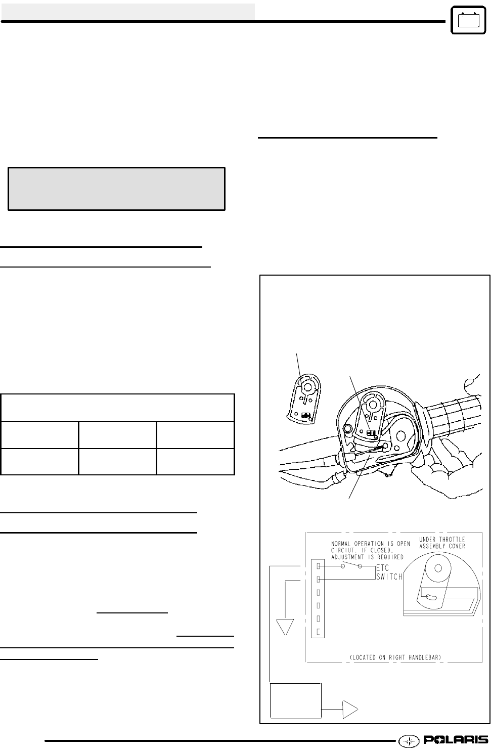
ELECTRONIC THROTTLE
CONTROL (ETC)
SWITCH
The Electronic Throttle Control (ETC) system is
designed to stop the engine of an ATV in the event of
a mechanical problem with the throttle mechanism.
The ETC switch is mounted independently of the
throttle actuator lever inside the throttle block
assembly. This is a normally closed
switch, and is
held in the open position (contacts are separated (as
shown below) by throttle cable tension. The
contacts
are “open” during normal operation regardless
of
throttle lever position.
In the event of a mechanical
problem in the throttle mechanism (cable tension is
lost), the switch contacts close, connecting the CDI
black wire to ground, which prevents ignition spark.
This is the same as turning the key or engine stop
switch “OFF”.
Test the ETC switch at the harness connector. NOTE:
Adjust throttle cable freeplay (ETC switch) and make
sure throttle mechanism is functioning properly before
testing the switch. Refer to Maintenance Chapter 2
for cable adjustment procedure.
ETC OPERATION TEST
Remove throttle block cover by carefully releasing all
tabs around edge of cover.
Place transmission in neutral and apply parking brake.
Start engine and open throttle lever slightly until
engine RPM is just above idle speed.
Hold throttle cable with fingers at point “A” as shown
below and release throttle lever. If the ETC system is
functioning properly, the engine will lose spark and stop.
Switch contacts are open
during normal operation
A
ETC switch contacts
are closed inafault
condition (throttle cable
slack).
Electronic Throttle Control (ETC) Switch
(Composite Throttle Housing)
Brn
Blk
Brn
CDI UNIT
Enfocus Software - Customer Support


