ENGINE
3.28
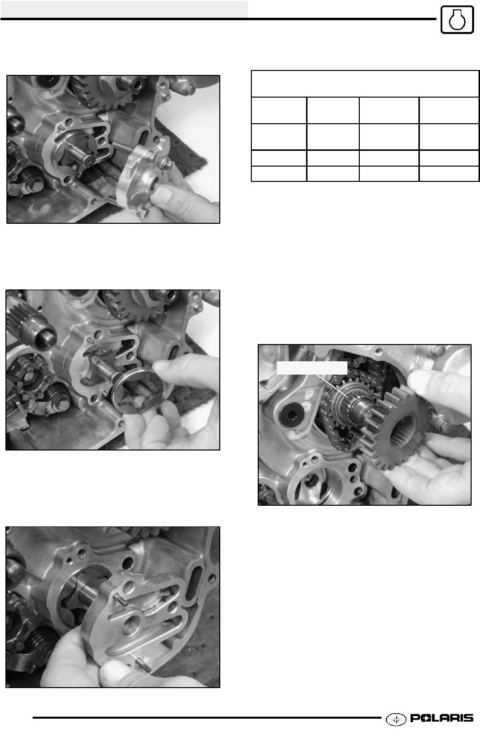
2. Remove the 3 bolts holding the oil pump cover.
Inspect the inside of the cover for wear or scoring.
3. Remove the outer pump rotor assembly. Inspect
for signs of scoring or excess wear. NOTE: Cross
pins for the pump rotors are loose and may
become lost. Keep pins in a secure location.
4. Remove the inner pump chamber and pump rotor
assembly. Inspect these components for wear or
scoring. NOTE: Dowel pins for the inner pump
body are loose and may become lost. Keep pins
in a secure location.
5. Replace any component that is found to be
damaged or worn.
OIL PUMP CLEARANCE
Limits are same as Standard
Body Feed/
Scavenge
.006--.008I .15 -- .21mm
Rotor Tip Feed/
Scavenge
Less than
.006I
Less than
.15 mm
Rotor Side Feed .0007--.003I .02 -- .08mm
Scavenge .002--.006I .05 -- .16mm
6. Installation: Reverse the procedures. Use
assembly lube or clean engine oil to coat the parts
before assembly. Tighten the cover bolts to 80-97
Inch Lbs.(9-11 Nm). Verify the pump turns freely
during and after torqueing bolts.
CRANKSHAFT DRIVE AND CAM GEAR
REMOVAL
1. Remove the crankshaft nut, washer and drive gear.
Note and whit e- mark t he double spline on both
gears and shaft for ease of reassembly .
Double Spline
2. Remove the cam gear and thrustwasher from the
crankshaft for inspection. Replace if damage or
excessive wear is present to the gear teeth or
splines.
3. Installation: Reverse the procedures and torque
nut to 59-74 Ft Lbs.(80-100 Nm).
Enfocus Software - Customer Support


