


1-17
KMD 250 Pilot's Guide
Section 1
Basic Operation
Rev 2 Apr/2004
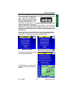
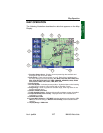
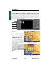
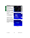
MAP OPERATION
The following illustration describes the data that appears on the Map
Display.
1 Function Status Icons - Displays icons representing data available and
displayed as well as sensor status.
2 Data Fields - These can be turned on or off. Each of the 5 windows can
be set to display one of the following; ALT, BRG, CDI, DIS, DEP TIME, DTK,
ESA, ETA WPT, ETE WPT, FLT TIME, GNDSPD, HEADING, MSA, NEAR
POS, PPOS, TIME, TKE, TRFC, TRK, WPT, XTK.
3 North Pointer
4 Aircraft Symbol - Indicates present position. Stylized airplane when heading
or track input is present, a plus symbol with no heading or track.
5 Range Rings - Outer ring radius is selected range, inner ring radius is one
half the selected range.
6 RESET STICK Soft Label
7 Traffic Symbol Overlay - Displayed when traffic avoidance system is installed.
8 Graphical METAR Icon Overlay - Displayed when FIS is installed and
subscription is valid.
9 LEGEND Soft Label
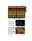
10 Current MAP Selection - VFR MAP (absolute altitude terrain shading), IFR
MAP (no terrain shading) or Relative Terrain Map (relative altitude terrain
shading).
11 Display Range - RNG:####.
1
6
2
3
4
5
10
7
9
8
11
Map Operation