


4-1
Rev 2 Apr/2004 KMD 250 Pilot's Guide
Section 4
Stormscope®
SECTION 4
WX-500 STORMSCOPE
®
OPERATION
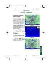
INTRODUCTION
The Bendix/King KMD 250 is capable of being interfaced to an L-3 WX-
500 Stormscope® Series II Weather Mapping Sensor. The WX-500
detects electrical discharges associated with thunderstorms within a 200
nm radius of the aircraft. The information is then sent to the KMD 250
and will display the location of the electrical discharges both on the map
displays and on a dedicated Stormscope® display.
For a detailed description of the WX-500 and how to interpret the light-
ning display and a list of error codes, please reference the WX-500
Stormscope® User’s Guide.
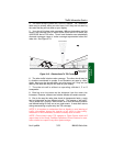
FUNCTIONAL DESCRIPTION
The antenna detects the electric and magnetic fields generated by intra-
cloud, inter-cloud, or cloud-to-ground electrical discharges that occur
within a 200 nm radius of the aircraft and sends the resulting "discharge
signals" to the processor. The processor digitizes, analyzes, and con-
verts the discharge signals into range and bearing data then stores the
data in memory. The WX-500 processor then communicates this infor-
mation to the KMD 250 as 'strikes' and 'cells'. The WX-500 updates the
KMD 250 every two seconds.
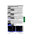
STORMSCOPE
®
FUNCTION STATUS ICONS
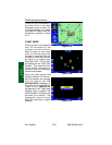
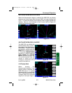
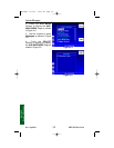
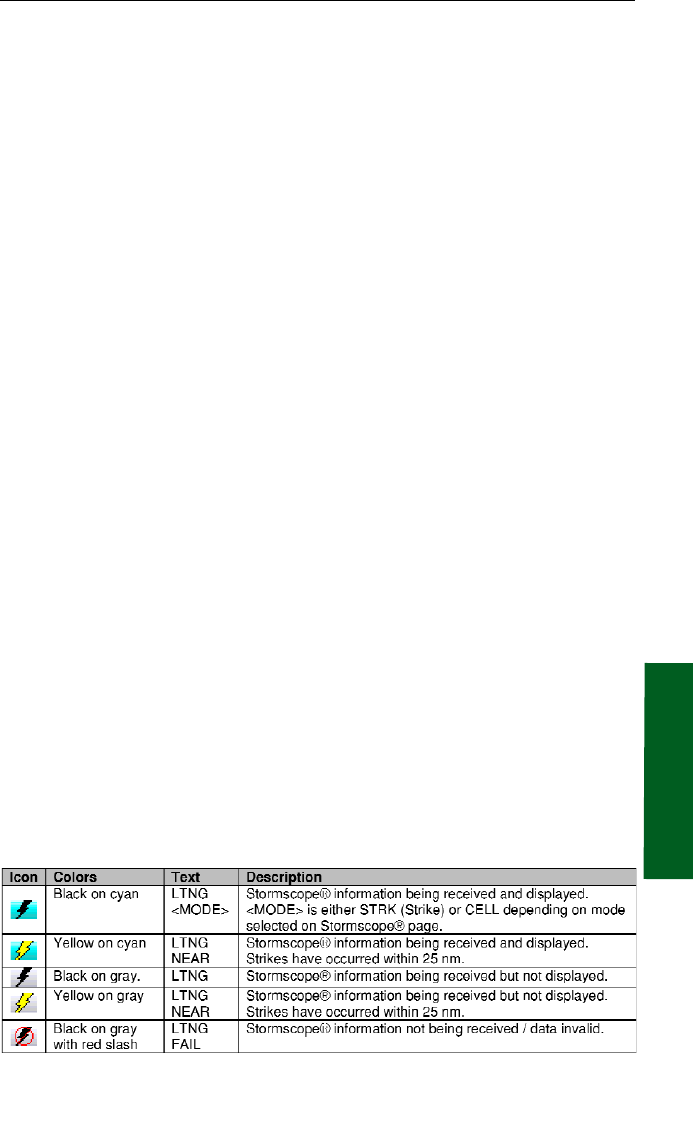
The Stormscope® Function Status Icons are located in the lower left of
the display. They are used to indicate whether or not the KMD 250 is
currently receiving and/or displaying Stormscope® information. The fol-
lowing table shows the various Stormscope® icons and their meanings:
Stormscope® Operation
Stormscope PG 8/13/07 10:00 AM Page 4-1