


4-5
Rev 2 Apr/2004 KMD 250 Pilot's Guide
Section 4
Stormscope®
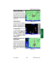
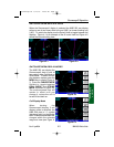
When moving from one range to the next, the 25 nm range is always
indicated by the solid inner ring to advise of close proximity to thunder-
storms. Also, notice that the discharge points are progressively larger on
the shorter ranges and smaller on the longer ranges. This effect makes it
easier to spot clusters of discharge points in any range.
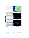
OPERATION IN STORMSCOPE® MODE WITH FLIGHT PLAN
If the KMD 250 is receiving Flight Plan information from the GPS and a
valid heading input is available, the Flight Plan lines and waypoints will
be displayed on the Stormscope® displays.
NOTE: In order to align the lightning strikes correctly to the flight plan
lines, heading information is necessary.
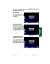
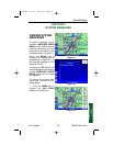
OPERATION IN MAP DISPLAY
The majority of the text in this section refers to the Stormscope® displays
on the KMD 250. It is also possible however to see thunderstorm cell or
strike data while in the Map Display. The Stormscope® overlay must be
enabled on Map Setup Page 6.
NOTE: Lightning data will only be displayed on the map if a heading ref-
erence is available in the form of an external heading reference input
(described previously).
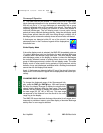
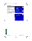
Any settings made while in the Stormscope® displays (i.e.
cell/strike mode, clear etc) will be carried over into the Map dis-
play. Lightning icons are shown here as they appear on the
Map display. The range at which lightning icons are displayed
is selectable on Map Setup Page 6.
CAUTION
Because the accuracy of the stormscope sensor is limited, do not
rely on the placement of lightning icons for map range settings less
than 25 nm.
Stormscope® Operation
Stormscope PG 8/13/07 10:00 AM Page 4-5