


8 - 46
–+
ELEC
SIGNALING SYSTEM
EAS00804
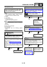
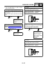
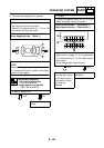
6. The fuel level gauge fails to operate.
YES
NO
YES
NO
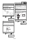
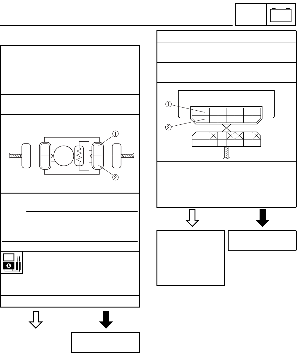
1. Fuel sender
• Drain the fuel from the fuel tank and remove
the fuel pump from the fuel tank.
• Connect the pocket tester (
Ω
×
10) to the
fuel sender terminals as shown.
Tester positive probe
→
green/white
1
Tester negative probe
→
black
2
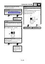
• Measure the fuel sender resistances.
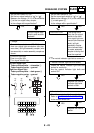
NOTE:
Measure the resistances when the float arm
is in contact with the full position and empty
position of the stopper.
Fuel sender resistance
Full position of the float
19 ~ 21
Ω
at 20 °C
Empty position of the float
139 ~ 141
Ω
at 20 °C
• Is the fuel sender OK?
Replace the fuel
pump.
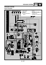
G/W
B
B
R/L
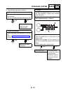
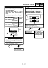
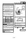
2. Voltage
• Connect the pocket tester (DC 20 V) to the
meter assembly coupler as shown.
Tester positive probe
→
green/white
1
Tester negative probe
→
black/white
2
• Set the main switch to “ON”.
• Measure the voltage (12 V) of green/white
1
and black/white
2
at the meter assem-
bly coupler.
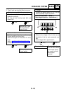
• Is the voltage within specification?
The wiring circuit
from the main switch
to the meter assem-
bly coupler is faulty
and must be
repaired.
Replace the meter
assembly.
R/W
G/WY/L
Lg
Y
Ch
Dg
L
R/G
B/W
Br/R
W