


1 - 26
GEN
INFO
FEATURES
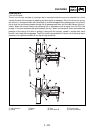
THREE-WAY CATALYTIC CONVERTER SYSTEM
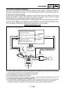
System outline
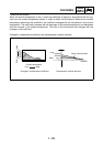
This is a highly efficient exhaust gas cleaning system that effects air-fuel control through a joint
effort by the FI system, O
2
sensor, and the three-way catalytic converter system. By effecting com-
prehensive control of the air-fuel ratio in this manner, this system reduces the CO, HC, and NOx in
the exhaust gases.
The FI system controls the mixture to an optimal air-fuel ratio (basic air-fuel ratio) that matches the
operating condition of the engine in order to realize an ideal combustion.
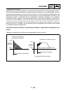
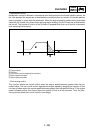
Furthermore, an O
2
sensor that detects the concentration of oxygen that remains in the exhaust gas
is provided in the exhaust pipe for the purpose of maximizing the performance of the three-way cat-
alytic converter and to clean the exhaust gas at a high degree of efficiency. Based on this data, the
ECU applies more precise compensation to the basic air-fuel ratio, in order to maintain the mixture
in the vicinity of the stoichiometric air-fuel ratio of 14.7:1.
Through the joint effort of these control systems, the exhaust gas is cleaned in a highly efficient
manner without sacrificing engine performance.
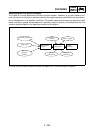
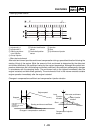
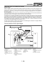
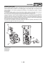
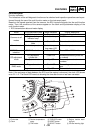
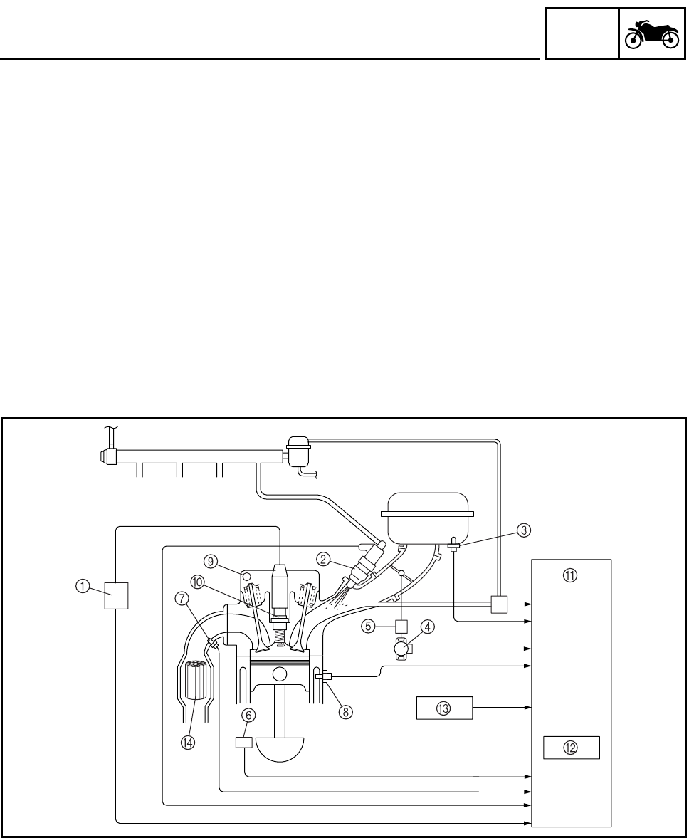
Three-way catalytic converter system diagram
1
Ignition coil
2
Injector
3
Intake temperature
sensor
4
Throttle position sen-
sor
5
Intake air pressure
sensor
6
Crankshaft position
sensor
7
O
2
sensor
8
Coolant temperature
sensor
9
Cylinder identification
sensor
0
Spark plug
A
ECU
B
Igniter
C
Atmospheric pressure
sensor
D
Catalytic converter