


7 - 21
FI
FUEL INJECTION SYSTEM
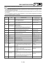
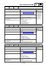
Code No. 19 Symptom Open circuit is detected in the input line from the sidestand switch to the
ECU.
Used diagnostic code No. 20 (sidestand switch)
Inspection operation item and probable cause Operation item and countermeasure Reinstatement
method
Defective sidestand switch Replace if defective.
Refer to “CHECKING THE SWITCHES” in
chapter 8.
If the transmission
is in gear, it is rein-
stated by retracting
the sidestand.
If the transmission
is in neutral, it is
reinstated by
reconnecting the
wiring.
Open or short circuit in wiring harness or sub
lead.
Repair or replace if there is an open or short
circuit.
(Between ECU and sidestand)
Connected state of connector
Inspect the coupler for any pins that may
have pulled out.
Check the locking condition of the coupler.
If there is a malfunction, repair it and connect it
securely.
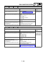
Main wiring harness ECU coupler
(No. 43 pin, black)
(Alarm coupler)
ECU coupler illustration
(Indicate No. 43 pin)
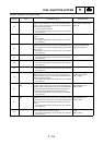
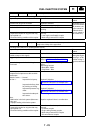
Code No. 21 Symptom Open or short circuit is detected from the coolant temperature sensor.
Used diagnostic code No. 06 (coolant temperature sensor)
Inspection operation item and probable cause Operation item and countermeasure Reinstatement
method
Installed state of sensor Check the installed area for looseness or
pinching.
Reinstated by turn-
ing the main switch
ON.
Defective coolant temperature sensor. Replace if defective.
Refer to “FUEL INJECTION SYSTEM” in
chapter 8.
Open or short circuit in wiring harness or sub
lead.
Repair or replace if there is an open or short
circuit.
Main wiring harness
Black/Blue - Black/Blue
Green/White - Green/White
Connected state of connector
Inspect the coupler for any pins that may
have pulled out.
Check the locking condition of the coupler.
If there is a malfunction, repair it and connect it
securely.
Coolant temperature sensor coupler
Main wiring harness ECU coupler
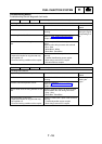
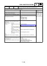
Code No. 22 Symptom Open or short circuit detected from the intake temperature sensor.
Used diagnostic code No. 05 (intake temperature sensor)
Inspection operation item and probable cause Operation item and countermeasure Reinstatement
method
Installed state of sensor Check the installed area for looseness or
pinching.
Reinstated by turn-
ing the main switch
ON.
Defective intake temperature sensor. Replace if defective.
Refer to “FUEL INJECTION SYSTEM” in
chapter 8.
Open or short circuit in wiring harness or sub
lead.
Repair or replace if there is an open or short
circuit.
Main wiring harness
Black/Blue - Black/Blue
Brown/White - Brown/White
Connected state of connector
Inspect the coupler for any pins that may
have pulled out.
Check the locking condition of the coupler.
If there is a malfunction, repair it and connect it
securely.
Intake temperature sensor coupler
Main wiring harness ECU coupler